
Advanced USB Hub PCB Fabrication and Turnkey Assembly

Figure 1.USB Hub PCB
Every USB hub — from a $10 travel dongle to a $500 industrial 16-port rack unit — runs on a single PCB that integrates a hub controller IC, per-port power switching, ESD protection, and impedance-controlled differential routing. The hub IC you choose, the stackup you specify, and the power architecture you design determine whether the product passes USB-IF certification on the first sample or fails in production. This guide gives you the specific part numbers, stackup rules, cost ranges, and layout constraints to get it right.
Table of Contents
- Hub Controller IC Selection: Every Major Part Number Compared
- Power Architecture: Bus-Powered vs Self-Powered vs USB-C PD Input
- PCB Stackup, Impedance Control and Differential Pair Routing
- ESD Protection, EMC Compliance and Connector Selection
- Product Configurations: 4-Port to 16-Port, Consumer to Industrial
- USB Hub PCB Fabrication and Assembly
1. Hub Controller IC Selection: Every Major Part Number Compared
The hub IC defines USB speed, port count, charging capability, and 60% of the total BOM cost. Choosing the wrong IC locks you into a product specification that cannot be changed without a board respin.
| Hub IC | USB Speed | Ports | Package | Per-Port Switch | BC1.2 | Best For |
|---|---|---|---|---|---|---|
| Genesys GL850G | 2.0 (480 Mbps) | 4 | SSOP-28 | External | No | Budget consumer hub, keyboard hub |
| Genesys GL852G | 2.0 | 4 | QFN-32 | External | No | Compact hub, charging station |
| Microchip USB2422 | 2.0 | 2 | QFN-36 | Internal | No | Embedded laptop hub, gateway |
| Microchip USB2517 | 2.0 | 7 | QFN-64 | External | Optional | 7-port desktop hub, KVM |
| Microchip USB5744 | 3.1 Gen 1 (5 Gbps) | 4 | QFN-64 | Internal | Yes | USB 3.0 hub with charging |
| VIA VL817 | 3.1 Gen 1 | 4 | QFN-76 | External | No | USB 3.0 dock, monitor hub |
| VIA VL822 | 3.2 Gen 1 | 4 | QFN-100 | External | No | USB-C docking station |
| TI TUSB8044 | 3.1 Gen 1 | 4 | BGA-144 | External | Optional | Industrial / professional hub |
| TI TUSB8044-Q1 | 3.1 Gen 1 | 4 | BGA-144 | External | Optional | AEC-Q100 automotive hub |
| Genesys GL3523 | 3.1 Gen 1 | 4 | QFN-88 | External | Yes | USB-C hub with PD pass-through |
For port counts above 7, cascade two hub ICs — one upstream feeding a second. This is how all 10-port, 12-port, and 16-port USB hubs are built. Two VL817s in cascade produce an 8-port USB 3.0 hub; two USB2517s cascade into a 14-port USB 2.0 hub.
For products with USB-C downstream ports supporting DisplayPort Alt Mode, pair the hub IC with a USB-C controller (TI TUSB544 retimer, VIA VL103) that handles CC pin negotiation and alt-mode lane switching. Single-chip hub + CC solutions are emerging but remain limited in port count and flexibility.
BGA hub ICs like the TUSB8044 require BGA PCB assembly with X-ray inspection — verify this capability before selecting a BGA-packaged hub IC.
2. Power Architecture: Bus-Powered vs Self-Powered vs USB-C PD Input
The power architecture is the number one source of USB hub product returns. A bus-powered hub that promises 4 ports but cannot power an external hard drive gets a 1-star review. Get the power budget right before layout.
Bus-powered. All current from the upstream host: 500 mA max (USB 2.0) or 900 mA max (USB 3.x). After hub IC consumption (~120 mA), each port of a 4-port hub gets roughly 100–200 mA. Enough for mice, keyboards, flash drives. Not enough for portable HDDs, webcams with LEDs, or any charging.
Self-powered. External adapter (5 V / 2.5–5 A barrel jack, or 12 V with on-board buck converter). Each port delivers full specification current: 500 mA (USB 2.0), 900 mA (USB 3.x), or 1.5–2.4 A with BC1.2 / Apple DCP / Qualcomm QC detection. Per-port power switch IC required: TI TPS2042 (dual, 500 mA), TI TPS2052B (dual, 800 mA), Diodes Inc AP2176 (single, adjustable).
USB-C PD input. Increasingly the standard for premium products. A USB-C PD controller (TI TPS65987, Cypress CYPD3177) negotiates 9 V, 15 V, or 20 V from the charger, then a buck converter steps down to 5 V for downstream VBUS. This enables both hub function and PD pass-through charging to a laptop — the product becomes a one-cable docking station.
Copper sizing for VBUS: at 1 oz copper, allow 30 mil trace width per ampere (10 °C rise). A 7-port hub at 900 mA per port = 6.3 A total — requires 190 mil (4.8 mm) trace or, more practically, a dedicated VBUS power plane on an inner layer. For charging hubs at 2.4 A × 7 ports (16.8 A), heavy copper PCB with 2 oz inner layers is the standard solution.
3. PCB Stackup, Impedance Control and Differential Pair Routing
USB 2.0 differential pairs (D+/D−) require 90 Ω ±10%. USB 3.x SuperSpeed pairs (TX/RX) require 90 Ω ±5%. These impedance targets, combined with port count, determine the minimum layer count:
| Product Type | Layers | Stackup | Impedance Method |
|---|---|---|---|
| USB 2.0, 4-port, bus-powered | 2 | Sig / GND | Microstrip on FR-4 |
| USB 2.0, 4–7 port, self-powered | 4 | Sig / GND / PWR / Sig | Microstrip, dedicated PWR plane |
| USB 3.0, 4-port | 4–6 | Sig / GND / Sig / PWR / GND / Sig | Stripline on inner layers |
| USB-C dock (hub + video + PD) | 6–8 | HDI with blind/buried vias | Stripline + HDI fanout |
| 16-port industrial hub | 6–8 | Heavy copper inner layers | Microstrip + wide VBUS planes |
Length matching: ≤5 mil intra-pair for USB 3.x, ≤50 mil for USB 2.0. Keep SuperSpeed pairs on inner layers between two ground planes (stripline) for shielding. Route USB 2.0 pairs on outer layers — less critical at 480 Mbps. Never route USB pairs across a ground plane split — the return current disruption causes immediate EMI failure.
For 4-layer USB hubs — the highest volume configuration — our 4-layer PCB fabrication uses standard stackups optimised for 90 Ω differential on 4 mil prepreg. For USB-C docking stations requiring 6–8 layers with HDI fanout, our HDI PCB capability supports 0.1 mm laser-drilled vias.

Figure 2. Various high-performance USB hub PCB solutions with customizable port counts ranging from 2 to 16+ ports for industrial and consumer applications.
4. ESD Protection, EMC Compliance and Connector Selection
Every external-facing USB connector needs ESD diodes within 1.5 mm of the connector pins — without exception. The first ESD event without protection destroys the hub IC.
USB 2.0 D+/D−: TVS array, capacitance ≤3 pF. TI TPD4S012, NXP IP4220CZ6, Nexperia PESD5V0U4BF.
USB 3.x TX/RX: Ultra-low-cap TVS, ≤0.3 pF. TI TPD4S214, Diodes Inc DT1452-02. Higher capacitance ESD diodes degrade 5 Gbps eye diagrams below USB-IF compliance limits.
VBUS: Bidirectional TVS rated for 5.5 V (or higher for PD). Bourns CDSOT23-SM712.
For EMC compliance (FCC Class B consumer, CE EN 55032): common-mode chokes on each USB pair reduce radiated emissions. Murata DLP21SN (USB 2.0), DLW32SH (USB 3.0). Place after ESD diodes, before the hub IC. Many USB 2.0 hub designs fail FCC without CMCs — add them from the start rather than as a post-certification fix.
Connector types by application: USB Type-A is standard for downstream ports on consumer hubs. USB Type-C is increasingly used for upstream (to host) and sometimes downstream (on premium docks). USB Type-B is rare but used in some industrial equipment. Micro-USB upstream is legacy — avoid in new designs. For connector mechanical reliability in products subject to frequent plug/unplug cycles, consider through-hole mounting tabs rather than pure SMT connectors. See our PCB connector guide for selection details.
5. Product Configurations: 4-Port to 16-Port, Consumer to Industrial
| Configuration | Hub IC | PCB | BOM (10K vol) | Retail Range | Target Market |
|---|---|---|---|---|---|
| 4-port USB 2.0 bus-powered | GL850G | 2-layer, 50×30 mm | $1.50–2.50 | $8–15 | Consumer, travel |
| 4-port USB 2.0 self-powered | GL852G + TPS2042 | 4-layer, 55×35 mm | $2.50–4.00 | $15–25 | Desktop, keyboard hub |
| 7-port USB 2.0 self-powered | USB2517 + 4× TPS2042 | 4-layer, 80×50 mm | $4.50–6.50 | $20–40 | Desktop, KVM extender |
| 4-port USB 3.0 | VL817 | 4-layer, 60×40 mm | $4.50–8.00 | $25–50 | Professional desktop |
| 4-port USB 3.0 + BC1.2 charging | USB5744 | 4-layer, 65×45 mm | $6.00–10.00 | $35–60 | Charging hub |
| USB-C 7-in-1 dock (hub+HDMI+ETH+PD) | VL822 + VL103 + RTL8153 | 6-8 layer HDI, 90×60 mm | $15–30 | $60–150 | Mobile professional |
| 8-port USB 3.0 industrial | 2× VL817 cascade | 6-layer, 150×80 mm | $18–35 | $150–350 | Factory automation, kiosk |
| 16-port USB 3.0 industrial | 2× VL817-Q8 cascade | 8-layer heavy copper, 200×120 mm | $35–60 | $300–600 | Device farm, signage, POS |
For extended temperature (−40 °C to +85 °C): use industrial-grade components and high-Tg PCB laminate (Tg ≥ 170 °C). For automotive: the TI TUSB8044-Q1 is the only major AEC-Q100-qualified USB 3.x hub IC.
For USB-C docking stations that combine hub, video, and charging: the PCB integrates 4–6 different controller ICs (hub, USB-C CC, DisplayPort retimer, Ethernet PHY, PD controller, audio codec). This is the most complex USB product category — layout requires careful separation of high-speed digital, analog audio, and high-current power sections on the PCB.

Figure 3. USB Hub PCB
6. USB Hub PCB Fabrication and Assembly
Three manufacturing requirements are specific to USB hub PCBs and must be verified with the fabrication partner before ordering:
Impedance verification. Every production batch must include TDR coupon testing to confirm 90 Ω ±5% (USB 3.x) or ±10% (USB 2.0) on differential pairs. FR-4 dielectric constant varies ±5–10% between material lots — without coupon verification, impedance drift goes undetected until functional test failures accumulate. Impedance-controlled PCB fabrication at Highleap includes TDR testing on every controlled-impedance order.
Mixed-technology assembly. USB hub boards combine SMT components (hub IC, ESD diodes, power switches, decoupling) with through-hole components (USB Type-A connectors, barrel jacks). Assembly sequence: SMT reflow first, then selective wave solder for through-hole. Reversing this sequence causes solder defects on the SMT side. Turnkey assembly with authorised-distributor component sourcing eliminates the counterfeit hub IC risk that plagues grey-market supply chains.
Functional test. Every assembled hub must be tested: USB enumeration on every port, data throughput at rated speed, per-port current delivery, and over-current protection trip point. A USB hub shipped without functional test will have 3–8% hidden defect rate from assembly — cold solder joints, marginal impedance, missing components. The cost to debug these in the field is 10–20× factory test cost.
Highleap Electronics manufactures USB hub PCBs from 5-unit prototypes to 100K+ production. Submit your USB hub PCB design for a quote — include Gerber files, BOM, volume, and certification scope.
Related: How to evaluate a USB hub PCB manufacturer · USB-C connector PCB integration · USB port expander products · USB converter design · USB expander systems

Recommended Posts
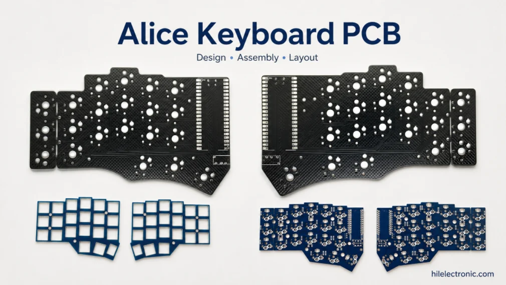
Alice Keyboard PCB Manufacturer | Custom Ergonomic Layout
An Alice keyboard PCB manufacturer must translate an...
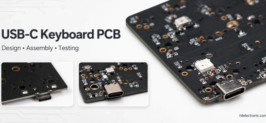
USB-C Keyboard PCB Manufacturer | ESD & Power Protection
A USB-C keyboard PCB manufacturer must control the...

Per-Key RGB Keyboard PCB Manufacturer & LED Assembly
A per-key RGB keyboard PCB manufacturer must control far...

Ortholinear Keyboard PCB Manufacturer | Custom Grid Layout
An ortholinear keyboard PCB manufacturer must preserve a...
How to get a quote for PCBs
Let‘s run DFM/DFA analysis for you and get back to you with a report. You can upload your files securely through our website. We require the following information in order to give you a quote:
-
- Gerber, ODB++, or .pcb, spec.
- BOM list if you require assembly
- Quantity
- Turn time
In addition to PCB manufacturing, we offer a comprehensive range of electronic services, including PCB design, PCBA, and turnkey solutions. Whether you need help with prototyping, design verification, component sourcing, or mass production, we provide end-to-end support to ensure your project’s success.
For PCBA services, please provide your BOM (Bill of Materials) and any specific assembly instructions. We also offer DFM/DFA analysis to optimize your designs for manufacturability and assembly, ensuring a smooth production process.