
Alice Keyboard PCB Manufacturer | Custom Ergonomic Layout
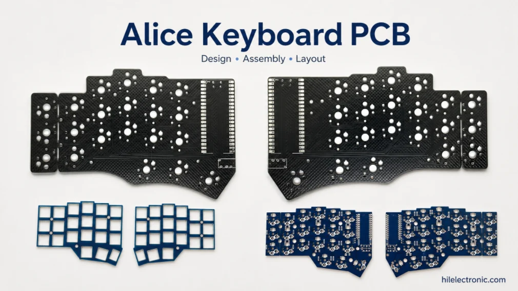
An Alice keyboard PCB manufacturer must translate an angled, center-separated layout into a repeatable electromechanical stack. Switch centers, thumb keys, stabilizers, PCB outline, plate, enclosure, USB position and firmware coordinates must use the same geometry. “Alice” describes a family of layouts rather than one universal mechanical standard.
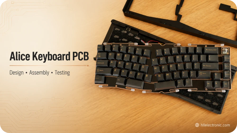
Highleap Electronics supports custom Alice and ergonomic keyboard PCB fabrication, SMT/THT assembly, hot-swap or soldered-switch versions, per-key RGB, USB-C, controller programming and complete key testing. Alice-style products are commonly single-piece keyboards with angled key groups; they should not automatically be described as physically split keyboards.
Start an Alice Keyboard PCB Quote
Share the layout or reference image, approximate board size, required quantity and whether you need bare PCB or PCBA. Existing Gerber, BOM, plate, enclosure or firmware files can be added when available. No schematic is required for the initial quotation.
Alice Layout Geometry and Design Inputs
Alice layouts angle the main typing groups and usually introduce a center gap, redistributed thumb keys and nonstandard bottom-row positions. Derivatives vary in key count, rotation, spacing and enclosure outline. Manufacturing files should therefore specify coordinates and dimensions rather than use the word “Alice” as a complete definition.
| Layout feature | Engineering decision | Production evidence |
|---|---|---|
| Left/right typing angle | Exact center coordinates and rotation | PCB and plate CAD use the same datum. |
| Thumb cluster | Key count, size and matrix assignment | Firmware and full-key test match physical labels. |
| Center gap | PCB outline, routing space and enclosure bridge | Mechanical fit is approved with plate and case. |
| Nonstandard keys | Stabilizer and optional switch footprints | Variant assembly drawing identifies fitted positions. |
Geometry should be frozen before electrical routing
Switch centers, key rotations and stabilizer axes should be approved before matrix routing and panelization. Late changes can move mounting holes, invalidate the plate, alter enclosure clearances and require firmware-coordinate updates. One coordinate datum should be used across the PCB, plate and enclosure CAD.
- Confirm key pitch, left/right rotation and center separation.
- Define every 1U, 1.25U, 1.5U, 2U and larger stabilized position.
- Document the thumb cluster and any optional split-space arrangement.
- Check keycap interference where angled groups meet.
- Identify which optional footprints belong to each sellable variant.
The geometry may support a differentiated typing posture, but comfort is user-specific. Product claims should describe the released layout rather than make unsupported medical or universal ergonomic statements.
PCB, Plate, Stabilizer and Enclosure Integration
Mechanical coordination is the principal manufacturing risk in an Alice project. Rotated switch footprints must align with plate cutouts, stabilizers must match the selected key sizes, mounting points must avoid traces and sockets, and the connector must remain accessible through the case.
| Integration area | Common failure | Control |
|---|---|---|
| Plate compatibility | Switches enter at an angle or bind | Overlay PCB and plate CAD; perform first-article fit. |
| Stabilizer placement | Long keys rub or cannot mount | Approve stabilizer type, orientation and keycap size. |
| Hot-swap sockets | Socket or switch pin conflicts with standoff/foam | Review bottom-side clearance and insertion load. |
| Enclosure clearance | Connector, encoder or daughterboard interference | Check 3D stack and cable path before fabrication. |
Hot-swap and soldered-switch versions need different checks
Soldered switches mainly depend on hole and plate alignment. Hot-swap versions add socket orientation, bottom-side clearance, insertion load and PCB support. When hot-swap is specified, the exact socket MPN and plate stack should follow the same controls used for hot-swap keyboard PCB manufacturing.
Foam, daughterboards and cable routing should be included in the 3D review. A case rib or foam layer that touches a socket, LED or USB cable can create intermittent faults after assembly even when the bare PCBA passes bench testing.
First-article approval should include the actual plate, stabilizers, switches, keycaps and enclosure whenever these parts are within project scope. A 2D overlay check alone cannot confirm insertion force, keycap clearance or connector access.
Matrix, Controller, QMK/VIA and Optional Features
The angled physical layout does not change the basic row-column architecture, but it makes coordinate control more important. The matrix map, diode direction, MCU pins, physical key labels and firmware positions must describe the same hardware revision. Optional layout footprints should not create duplicate or ambiguous key events.
For a detailed electrical release, the keyboard matrix design should define row/column names, diode orientation, test access and the rollover target. The controller package should also preserve reset, boot and programming access after the PCB is installed in the case.
QMK and VIA production requirements
QMK and VIA are common because Alice thumb clusters and layers benefit from configurable keymaps. Production programming should control the bootloader, application binary, keyboard definition, VIA data, USB descriptors and firmware checksum. VIA recognition should be tested on the programmed board rather than assumed from a configuration file.
Optional hardware features
- Per-key RGB: physical LED indices must match the angled key positions, and maximum-current behavior should be tested.
- USB-C: connector placement must align with the enclosure and include the approved CC, ESD and power implementation.
- Encoders and displays: shafts, windows and component heights require mechanical keepouts.
- Wireless: battery location, antenna clearance, charging path and enclosure material affect the design.
- Split derivatives: truly two-piece products need an interconnect, protection and independent half testing; these are not assumed for a standard single-piece Alice PCB.
Feature-heavy variants may justify four PCB layers for routing and power distribution, while simpler designs often use two. Layer count should follow DFM, return-path and power review rather than the keyboard shape alone.
Alice PCB Manufacturing, Programming and Testing
A coordinated manufacturing route prevents the PCB, plate and firmware from being approved independently and then failing at final assembly.
- Review PCB outline, switch centers, plate, stabilizers, enclosure and connector position together.
- Fabricate and electrically test the bare PCB, including internal cutouts and mounting features.
- Assemble diodes, controller, USB-C, RGB and approved sockets or THT switches.
- Inspect both sides when components are placed on both sides of the PCBA.
- Program the released bootloader and QMK/VIA or customer firmware.
- Test every standard, thumb and optional key position against the approved coordinate map.
- Verify RGB, encoders, display, USB orientation, bootloader entry and current draw where applicable.
- Complete plate and enclosure fit checks on the pilot build when included in scope.
Testing must cover the nonstandard positions
A generic keyboard fixture can miss rotated thumb keys or optional split-space positions. The test program should identify each physical coordinate and expected logical event. For universal PCBs, every assembly variant needs its own population map and test profile.
Mechanical acceptance should include stabilizer motion, keycap clearance, switch seating and connector access. Cosmetic criteria may also cover solder-mask appearance around the center gap, visible LEDs and alignment of branded graphics.
These controls can be combined with broader keyboard PCB production, including component sourcing, firmware revision control and repeat-order traceability.
Prototypes, Layout Variants and Volume Production
The prototype stage should prove geometry, plate fit, firmware coordinates and user-facing features. A pilot batch then confirms assembly yield, socket or switch process, test-fixture coverage and packaging. Volume production should begin only after the PCB, mechanical stack and firmware package are frozen together.
Variant control prevents mixed-build errors
One PCB may support several bottom rows, thumb clusters, switch types or connector options. Shared tooling can reduce cost, but only when each SKU has a controlled BOM, assembly drawing, firmware image, label and test configuration. Unused footprints should be clearly marked so production and field service can distinguish intentional no-fit positions from defects.
| Cost or schedule driver | Why it matters | Control |
|---|---|---|
| Large or irregular outline | Reduces panel utilization. | Review panelization before finalizing edge features. |
| Custom plate and enclosure | Uses a separate mechanical supply chain. | Develop mechanical and electronic parts in parallel. |
| Multiple variants | Adds setup, inventory and test complexity. | Freeze SKU-specific release packages. |
| Programming and full-key test | Adds fixture and cycle time. | Use repeatable fixtures and revision-controlled test software. |
Pricing is driven by board size, layer count, socket or switch population, RGB quantity, controller complexity, test time, order quantity and mechanical integration scope. Stable revisions and repeatable fixtures generally create larger savings than removing isolated quality controls.
Alice Keyboard PCB FAQ
Is an Alice keyboard the same as a split keyboard?
Not necessarily. Most Alice-style keyboards are single-piece products with angled left and right key groups. Physically split derivatives exist but require a separate interconnect and enclosure architecture.
Can an Alice PCB support QMK and VIA?
Yes, when the MCU, bootloader, matrix, keyboard definition and VIA configuration are released for the same PCB revision and verified after programming.
Can Alice keyboards use hot-swap sockets?
Yes. The exact socket, switch, plate, PCB thickness, stabilizer arrangement and bottom-side clearance must be validated together.
What is the most common manufacturing failure?
Mismatch between PCB coordinates, plate cutouts, stabilizers, enclosure features and firmware positions. Coordinated first-article fit and full-key testing reduce this risk.
Can one PCB support several Alice layouts?
Yes, but each fitted variant needs an unambiguous assembly drawing, firmware map, label and test profile.
Discuss an Alice Keyboard PCB Project
Provide the layout or reference, approximate board size, quantity and required scope. Existing PCB, plate and firmware files can be added at the engineering stage.

Recommended Posts

TMM4 Filter PCB Manufacturing
TMM4 filter PCB manufacturing is controlled by the...

TMM3 PCB Manufacturing for RF Modules
TMM3 PCB manufacturing is most useful where the RF module...

TMM6 PCB Fabrication
TMM6 fabrication is the process-control page for a mid-Dk...

TMM10 PCB Manufacturing for Compact RF Designs
Table of contentsHow TMM10 Shrinks RF StructuresTMM10 vs...
How to get a quote for PCBs
Let’s run DFM/DFA analysis for you and get back to you with a report. You can upload your files securely through our website. We require the following information in order to give you a quote:
-
- Gerber, ODB++, or .pcb, spec.
- BOM list if you require assembly
- Quantity
- Turn time
For PCBA services, please provide your BOM (Bill of Materials) and any specific assembly instructions. We also offer DFM/DFA analysis to optimize your designs for manufacturability and assembly, ensuring a smooth production process.