
Best USB Converter PCB and PCBA Services 2026

Figure 1. USB Converter
A USB converter bridges the gap between the USB port on your computer and the interface your device actually needs — serial, Ethernet, HDMI, audio, CAN bus, or GPIO. Each bridge IC defines a different PCB design, different compliance requirement, and different market. This guide covers every major USB converter category with specific IC part numbers, BOM ranges, and the PCB constraints that matter for each.
Table of Contents
- USB to Serial: UART, RS-232, RS-485 and RS-422
- USB to Ethernet, HDMI, DisplayPort and VGA
- USB to Audio, CAN Bus, GPIO, I²C and SPI
- USB-C Multi-Port Docks: The Convergence Product
- PCB Design Rules That Apply to All USB Converters
- Manufacturing USB Converter PCBs at Highleap
1. USB to Serial: UART, RS-232, RS-485 and RS-422
The single largest-volume USB converter category in industrial and embedded applications.
| Converter Type | Bridge IC | Output | Isolation | PCB Layers | BOM (vol) |
|---|---|---|---|---|---|
| USB to TTL UART | FTDI FT232R, CP2102, CH340G | 3.3 V / 5 V logic | None | 2 | $0.50–2.50 |
| USB to RS-232 | FT232R + MAX3232 | ±5 V to ±15 V | Optional | 2–4 | $1.50–4.00 |
| USB to RS-485 | FT232R + MAX485 | Differential ±7 V | Recommended | 4 | $4.50–12.00 |
| USB to RS-422 | FT232R + SN75176 | Differential, full duplex | Recommended | 4 | $4.50–12.00 |
| Multi-port (4/8 ch) | Hub IC + 4/8× bridge | Mixed | Per-channel | 4–6 | $25–80 |
For industrial RS-485 and RS-422 converters, galvanic isolation is the critical reliability feature. A bus fault on the RS-485 line can destroy the host PC’s USB port if isolation is inadequate. Reinforced isolation (2.5 kV continuous, 10 kV transient per IEC 60664-1) requires specific high-voltage PCB creepage and clearance distances between the USB-side and RS-485-side circuits. Digital isolators: Silicon Labs Si8410, Analog Devices ADuM1201.
Counterfeit FTDI FT232R and CH340 chips are a documented supply chain problem. FTDI firmware updates have been known to brick counterfeit chips, causing customer returns. Source through authorized distributors only. Authorised component sourcing eliminates this risk.
2. USB to Ethernet, HDMI, DisplayPort and VGA
USB to Gigabit Ethernet. Bridge ICs: Realtek RTL8153 (USB 3.0, most common), ASIX AX88179, Microchip LAN7800. The bridge includes USB interface, Ethernet MAC, and integrated PHY. External components: Ethernet magnetics module + RJ-45 jack. PCB: 4-layer, 40 × 25 mm. BOM: $3.50–7.50. Applications: laptops without Ethernet, Raspberry Pi networking, thin clients.
USB-C to HDMI (4K60). Uses DisplayPort Alt Mode over USB-C, converted to HDMI via a protocol converter IC: Parade PS176, Realtek RTD2172, Lontium LT8711. The converter takes DisplayPort input from the USB-C SuperSpeed lanes and outputs HDMI. PCB: 4–6 layer with HDI for USB-C fanout, 50 × 30 mm. BOM: $6.50–15.00.
USB-C to dual HDMI (4K60 × 2). Requires a DisplayPort 1.4 MST (Multi-Stream Transport) hub IC between the USB-C input and two HDMI output converters. PCB: 6–8 layer, 70 × 40 mm. BOM: $15–30. This is a premium product segment driven by remote work multi-monitor setups.
USB to VGA. Uses a DisplayLink DL-3500 or similar USB display adapter IC — the host PC treats the adapter as a virtual GPU. Output: analog VGA via on-board DAC. PCB: 4-layer, 40 × 30 mm. BOM: $8–20. Declining volume as VGA monitors are retired. For analog video sections, mixed-signal PCB design techniques (separated analog and digital ground, filtered power for DAC) apply.
3. USB to Audio, CAN Bus, GPIO, I²C and SPI
USB audio interfaces. Bridge ICs: TI PCM2906 (basic stereo), Cirrus Logic CS42L42 (headset codec), ESS Sabre ES9018 (audiophile DAC). Range: $5 USB headset adapters to $1,000 studio interfaces. PCB complexity scales with audio quality: basic 2-layer for consumer, 4–6 layer with analog/digital ground separation and shielded connectors for professional. Audio amplifier PCB design principles apply to headphone output stages.
USB to CAN bus. Used in automotive diagnostics (OBD-II), industrial CAN networks, and factory automation. Bridge: Microchip MCP2515 CAN controller + MCP2561 transceiver, or single-chip Kvaser solutions. Galvanic isolation mandatory for industrial CAN (eliminates ground loops between vehicle/machine and PC). PCB: 4-layer with isolation barrier, 70 × 40 mm. BOM: $10–25.
USB to GPIO / I²C / SPI. Used by embedded engineers for development and test. Bridge ICs: FTDI FT2232H (dual-channel, SPI + JTAG), Microchip MCP2221A (I²C + GPIO), Cypress CY7C68013A (high-speed bulk transfer). PCB: 2–4 layer, 50 × 30 mm with breakout pin headers. BOM: $3–10.
USB to wireless (Bluetooth, Wi-Fi, 4G/5G). Now dominated by single-chip modules — the bridge IC and radio are integrated. The PCB provides USB connector, power regulation, and antenna (PCB trace antenna, chip antenna, or u.FL for external). PCB: 2–4 layer, often 30 × 20 mm or smaller. BOM dominated by the wireless module ($5–50).

Figure 2. Various Types of USB Converters
4. USB-C Multi-Port Docks: The Convergence Product
The fastest-growing USB converter category combines multiple bridges into a single product — a USB-C docking station. One cable from the laptop provides: USB data (hub), video (HDMI/DP), network (Ethernet), audio, card reader, and power (PD pass-through). Typical IC stack:
| Function | Typical IC | PCB Requirement |
|---|---|---|
| USB hub (4 downstream) | VIA VL822 | 90 Ω diff pairs × 8 |
| USB-C controller (CC, Alt Mode) | TI TUSB544, VIA VL103 | CC routing, SBU lines |
| USB PD controller | TI TPS65987 | VBUS power path, OVP |
| DisplayPort retimer | Parade PS8743 | High-speed DP lanes |
| HDMI converter | Parade PS176 | TMDS differential pairs |
| Gigabit Ethernet | Realtek RTL8153 | Ethernet magnetics + RJ-45 |
| Audio codec | Realtek ALC4042 | Analog ground separation |
PCB: 6–8 layer HDI, approximately 100 × 60 mm. BOM: $25–60. Retail: $80–250. This is the most complex consumer USB product — layout requires careful partitioning of high-speed digital, analog audio, and high-current power sections. HDI PCB manufacturing with blind/buried vias is standard for this product category.
5. PCB Design Rules That Apply to All USB Converters
Regardless of the specific converter type, every USB converter PCB shares these requirements on the USB-side:
USB differential pair impedance: 90 Ω ±10% (USB 2.0) or ±5% (USB 3.x). Use impedance-controlled PCB fabrication with TDR-verified coupons.
ESD protection: TVS diode arrays on every external USB connector, within 1.5 mm of pads. No exceptions — the first ESD event without protection destroys the bridge IC.
Decoupling: 100 nF X7R ceramic within 2 mm of every bridge IC power pin. 10 µF bulk on each major rail. For bridge ICs operating above 1 GHz internally, additional 1–10 nF capacitors span mid-to-high frequency.
Crystal/oscillator placement: Most USB bridge ICs require a 12 MHz crystal (±50 ppm) with 18 pF load capacitors. Place the crystal within 5 mm of the IC with short, symmetric traces. Route ground copper under the crystal to reduce noise coupling.
Output interface compliance: Ethernet requires IEEE 802.3 magnetics; HDMI requires TMDS impedance control; CAN requires ISO 11898 transceiver compliance. Each output adds its own set of PCB constraints — the USB side is only half the design.
Thermal management: Bridge ICs dissipating over 1 W (Ethernet, video, audio with headphone amp) need thermal vias under the IC connecting to inner ground planes. Without them, the IC runs above its rated junction temperature and either throttles performance or fails prematurely.
6. Manufacturing USB Converter PCBs at Highleap
Highleap manufactures USB converter PCBs across all categories — from $0.50 BOM USB-to-UART cables to $50+ BOM USB-C docking stations.
Volume flexibility: 50-unit prototype runs for specialty industrial converters to 100K+ for consumer products. Same DFM and quality processes at every tier.
Mixed-technology assembly: SMT (bridge IC, ESD, decoupling) + through-hole (USB connectors, RJ-45, DB9, terminal blocks, barrel jacks). SMT reflow first, then selective wave solder for TH connectors. Turnkey PCB assembly handles all component sourcing through authorised channels.
Functional test: Custom test fixture per product: USB enumeration, throughput on converted interface (UART baud accuracy, Ethernet packet loss, video output validation), isolation test for industrial converters.
Request a USB converter PCB quote — include converter type, volume, and any certification requirements.
Related: USB hub PCB design · USB-C connector integration · USB expander systems · USB port expander products

Recommended Posts
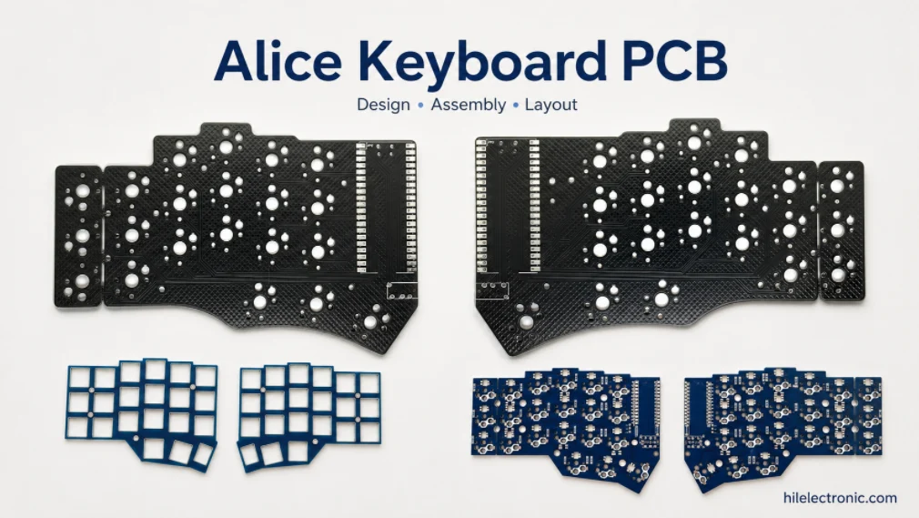
Alice Keyboard PCB Manufacturer | Custom Ergonomic Layout
An Alice keyboard PCB manufacturer must translate an...
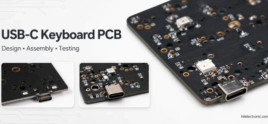
USB-C Keyboard PCB Manufacturer | ESD & Power Protection
A USB-C keyboard PCB manufacturer must control the...

Per-Key RGB Keyboard PCB Manufacturer & LED Assembly
A per-key RGB keyboard PCB manufacturer must control far...

Ortholinear Keyboard PCB Manufacturer | Custom Grid Layout
An ortholinear keyboard PCB manufacturer must preserve a...
How to get a quote for PCBs
Let‘s run DFM/DFA analysis for you and get back to you with a report. You can upload your files securely through our website. We require the following information in order to give you a quote:
-
- Gerber, ODB++, or .pcb, spec.
- BOM list if you require assembly
- Quantity
- Turn time
In addition to PCB manufacturing, we offer a comprehensive range of electronic services, including PCB design, PCBA, and turnkey solutions. Whether you need help with prototyping, design verification, component sourcing, or mass production, we provide end-to-end support to ensure your project’s success.
For PCBA services, please provide your BOM (Bill of Materials) and any specific assembly instructions. We also offer DFM/DFA analysis to optimize your designs for manufacturability and assembly, ensuring a smooth production process.