
Per-Key RGB Keyboard PCB Manufacturer & LED Assembly
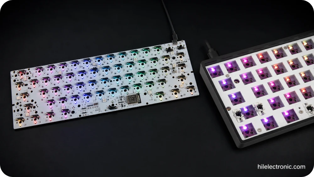
A per-key RGB keyboard PCB manufacturer must control far more than LED placement. A production-ready board needs a defined LED architecture, current budget, power-distribution strategy, optical stack, firmware behavior, thermal margin and complete array test. A prototype can appear correct with a short animation and still reset, show color variation or overheat when every LED is driven at high brightness.
Highleap Electronics manufactures bare keyboard PCBs and assembled RGB keyboard PCBAs with addressable or matrix-driven LEDs, MCU and driver circuitry, USB-C, hot-swap socket assembly, wireless functions and customer firmware. The scope can start with a simple product description and quantity, then progress to engineering review, first articles, programming and repeat production after the design is released.
A typical mechanical keyboard PCB is commonly a two-copper-layer rigid board, although routing density, radio functions or power integrity may justify additional layers. This is separate from assembly-side count: LEDs, sockets, diodes and controllers may be populated on both sides of the same PCB. Quotations and assembly drawings should distinguish two-layer PCB from double-sided component assembly.
Start a Per-Key RGB Keyboard PCB Quote
Tell us the keyboard size, approximate key count, required quantity and whether you need bare PCB or assembled PCBA. A photo, layout drawing, Gerber or BOM can be attached when available, but incomplete information is acceptable and no PCB schematic is required for an initial quote.
Per-Key RGB Architectures and Buying Specifications
Per-key lighting is normally implemented with addressable RGB LEDs, matrix-driven LEDs or dedicated constant-current drivers. The correct architecture depends on key count, refresh behavior, available MCU resources, brightness target, USB-C power budget and firmware platform. An LED marked “RGB” is not automatically compatible with an existing footprint or timing protocol; package pinout, data direction, voltage range and reflow profile must match the released design.
| Architecture | Advantages | Production questions |
|---|---|---|
| Individually addressable LEDs | Simple daisy-chain control and independent effects | Confirm protocol, data direction, bypassing, first-LED protection and failure behavior. |
| Matrix-multiplexed RGB | Can reduce serial-chain dependency | Confirm row/column drivers, duty cycle, ghost illumination and firmware timing. |
| Dedicated LED driver ICs | Controlled current and diagnostic options | Confirm channel count, thermal load, I²C/SPI addressing and test access. |
The production package should define LED orientation in centroid data, reference-designator visibility, driver addresses and the relationship between physical key positions and firmware indices. This avoids a board that lights correctly in hardware but displays effects on the wrong keys.
Per-Key RGB Keyboard PCB Buying Specifications
Before volume pricing is fixed, the main commercial decision is whether Highleap is supplying a bare board, an LED-populated subassembly or a complete programmed keyboard PCBA. The number of LEDs alone does not define cost. LED package, driver topology, assembly side, brightness target, current limiting, diffuser geometry and test time can change the manufacturing route substantially.
| Quotation item | Why it affects manufacturing | Low-friction information for the first inquiry |
|---|---|---|
| Keyboard format | Determines LED quantity, board dimensions, panel utilization and fixture size. | Approximate key count or a reference layout is sufficient. |
| Lighting architecture | Addressable LEDs, external drivers and multiplexed arrays use different BOMs, routing and firmware. | State “per-key RGB” and provide the LED or reference product only if known. |
| Power source | USB-only, battery and dual-mode products have different current and brightness limits. | Describe wired, wireless or tri-mode operation. |
| Supply scope | Bare PCB, LED assembly, full PCBA, programming and box build require different cost models. | Choose the closest scope; details can be refined later. |
| Order stage | Prototype, pilot and stable volume orders use different material purchasing and fixture amortization. | Give an approximate first quantity and expected follow-on volume. |
Power Budget, Data Integrity and Voltage Drop
LED topology and data integrity
Individually addressable LEDs simplify per-key control but create a serial data path in which one orientation, solder or output failure can interrupt downstream devices. Matrix-driven or dedicated-driver architectures distribute risk differently and require their own channel, address and current-setting controls.
Current budget and approved maximum-load mode
The electrical maximum, firmware brightness and marketed brightness are not the same value. The production package should define an approved worst-case pattern, LED current, controller and peripheral load, connector limit, cable drop, regulator efficiency and design margin. A firmware brightness cap may be part of the released product specification, but it should not hide an undersized power path.
Power distribution and voltage drop
Long current paths, narrow neck-downs, insufficient copper or marginal connectors can create color shift, brightness gradients or MCU brownouts. Rail width, plane continuity, via count, injection points and local decoupling should be reviewed together. Wireless versions also require battery-path, regulator and runtime analysis.
Planning relationship: total input current ≈ active LEDs × approved LED current + controller/peripheral current + design margin. Final values must come from the selected LED, power architecture and acceptance mode.
| Risk | Typical symptom | Control |
|---|---|---|
| Long power path | Dim or color-shifted LEDs at remote keys. | Wider rails, distributed injection and measured voltage-drop limits. |
| Insufficient USB margin | Reset or enumeration failure at high brightness. | Defined current cap and maximum-load USB test. |
| Driver or regulator heating | Brightness instability or thermal shutdown. | Dissipation, copper area, component rating and enclosure-temperature review. |
| Data-chain fault | Flicker or downstream LEDs remain off. | Orientation control, decoupling, routing and address-walk testing. |
LED Placement, Optical Consistency and Mechanical Stack
Electrical pass does not guarantee an acceptable lighting product. LED center position, package height, switch housing, plate opening, diffuser material, foam and keycap translucency all affect perceived brightness and color. A board can pass current testing yet show one key as darker because the LED is off-center or partially blocked.
- Approve LED-to-switch orientation and center offset.
- Control solder volume so side-view or reverse-mount LEDs do not tilt.
- Check plate and diffuser apertures against the actual LED package.
- Use a golden sample for cosmetic comparison when uniformity is a sellable feature.
- Define whether cosmetic testing is visual, camera-based or limited to electrical operation.
For double-sided assemblies, the reflow sequence must protect LEDs and sockets already mounted on the first side. Component mass, adhesive use, second-pass peak temperature and board support are reviewed during process planning.
Electrical pass results do not guarantee visual consistency. LED-to-switch distance, north-facing or south-facing orientation, switch housing, plate cutout, diffuser, keycap material and solder height affect perceived brightness and color. Highleap therefore treats the PCB, switch, plate and optical stack as one released configuration for pilot approval.
- Use the exact LED package and approved optical orientation.
- Control solder paste and component seating to reduce height variation.
- Inspect blocked or shadowed LEDs after plate and switch installation.
- Define whether acceptance is electrical only or includes visual uniformity against a golden unit.
Assembly, Firmware Test Modes and Wireless Trade-Offs
A typical LED PCB assembly route is bare-board electrical test, solder-paste inspection where required, first-side SMT, second-side SMT when the design uses components on both sides, SMT AOI, THT or connector operations, cleaning controls, firmware loading and functional test. Process order depends on the mass and heat sensitivity of sockets, USB connectors, displays and other mechanical parts.
RGB Firmware Test Modes and Complete Array Testing
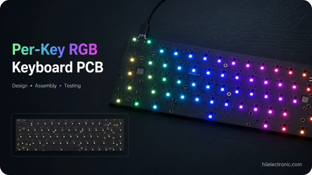
A keyboard PCBA RGB production test should use a deterministic sequence rather than a continuously changing decorative animation. A practical mode displays red, green and blue separately, runs a defined mixed-color or white load, and then walks each physical address. This exposes missing channels, swapped color order, chain interruptions, wrong mapping and current-related resets.
- Program the approved bootloader and application or manufacturing image.
- Enumerate the keyboard and verify the released device identity.
- Address every physical LED through red, green, blue and the approved load state.
- Measure idle and maximum-pattern current and check remote-rail voltage where required.
- Operate keys, encoders, displays and lighting together.
- Record failures by key position or reference designator for rework.
The test mode, brightness limit and mapping file must be tied to the hardware and firmware revision. Sampling only a few LEDs is insufficient for a per-key product.
Per-Key RGB on Wireless Keyboard PCBAs
Wireless RGB products need an explicit priority between brightness, animation, latency and battery life. Firmware may limit LED current in battery mode and allow higher brightness over USB. The charger, battery protection, regulator and power-path components must tolerate the approved operating states.
Production testing can measure charge current, active RGB current, idle current and sleep current. A single “battery works” check is insufficient when RGB leakage or an always-powered LED rail can reduce shelf or standby life.
Failure Analysis, Cost Planning and Production Controls
| Observed failure | Likely causes | Production response |
|---|---|---|
| All LEDs after one key are off | Open data path, reversed LED, solder bridge or damaged device. | Probe data in/out by position, inspect orientation and replace the first failed node. |
| Board resets at high brightness | USB current limit, rail drop, regulator thermal limit or firmware peak load. | Measure VBUS and internal rails under the approved maximum pattern; adjust power or brightness strategy. |
| One color channel is missing | LED damage, insufficient wetting, local trace fault or firmware mapping error. | Separate electrical channel failure from keymap/animation configuration. |
| Visible color or brightness mismatch | LED bin variation, tilt, optical obstruction, voltage gradient or diffuser inconsistency. | Use approved LED lots, mechanical alignment control and golden-unit comparison. |
| Intermittent RGB after flexing | Cracked solder joint, unsupported PCB area or enclosure load. | Inspect under controlled flex, improve support and review pad geometry/reflow. |
Customization, Volume Pricing and Supply Planning
Prototype orders should establish LED orientation, optical appearance, firmware test mode and peak-current behavior. Pilot production then verifies process repeatability, fixture coverage and cosmetic acceptance before volume release.
Customization may include LED package, underglow, logo lighting, diffuser geometry, keyboard layout, solder mask, firmware effects and branded startup behavior. Each sellable variant should retain a controlled PCB revision, PCB assembly BOM and release files, firmware checksum and test profile.
Volume pricing improves through stable LED purchasing, panel utilization, automated placement, reduced setup cost per board and fixture amortization. LED, MCU, USB connector and laminate substitutions require package, brightness, electrical-load, firmware and optical validation.
RGB Keyboard PCBA Production Controls
When specified for the order, production records can cover incoming LED verification, first-article orientation, AOI, firmware revision, complete array test, maximum-pattern current and failure segregation. The acceptance pattern and brightness setting should be revision-controlled so repeat orders are tested under the same conditions.
Per-Key RGB Keyboard PCB FAQ
Can a per-key RGB keyboard PCB use two layers?
Yes. Many designs use a two-layer board, but four layers may be preferable when routing density, power distribution, wireless circuits or return paths require it.
Does double-sided PCB mean components are assembled on both sides?
No. A two-layer PCB describes copper on both sides. Double-sided assembly describes components placed on both sides of the PCBA; a product may use either or both.
How should maximum RGB current be specified?
Use the selected LED datasheet, approved simultaneous-lighting condition, controller load, power-path loss and margin. State any firmware brightness limit as an acceptance condition.
How is every LED tested?
A production fixture or test firmware addresses each physical LED through defined colors while current, mapping and interaction with keyboard functions are checked.
Discuss a Per-Key RGB Keyboard Project
Start with the keyboard size, approximate quantity, wired or wireless mode and whether Highleap should supply bare PCB or PCBA. Send any files or photos already available; a complete file package and PCB schematic are not required for the first quotation.

Recommended Posts

TMM4 Filter PCB Manufacturing
TMM4 filter PCB manufacturing is controlled by the...

TMM3 PCB Manufacturing for RF Modules
TMM3 PCB manufacturing is most useful where the RF module...

TMM6 PCB Fabrication
TMM6 fabrication is the process-control page for a mid-Dk...
TMM13i PCB Manufacturing
TMM13i PCB manufacturing is aimed at ultra-compact RF...
How to get a quote for PCBs
Let’s run DFM/DFA analysis for you and get back to you with a report. You can upload your files securely through our website. We require the following information in order to give you a quote:
-
- Gerber, ODB++, or .pcb, spec.
- BOM list if you require assembly
- Quantity
- Turn time
For PCBA services, please provide your BOM (Bill of Materials) and any specific assembly instructions. We also offer DFM/DFA analysis to optimize your designs for manufacturability and assembly, ensuring a smooth production process.