
Conference Webcam PCB Fabrication and Assembly for OEMs
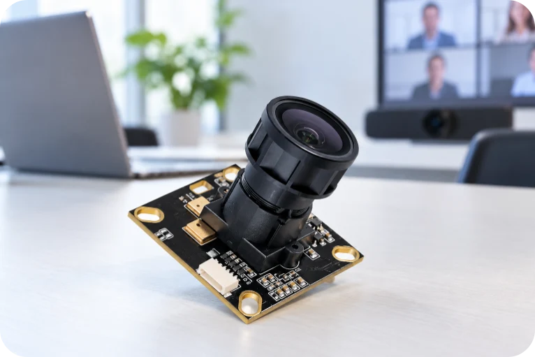

On a conference webcam assembly drawing, the camera connector’s mating side and the microphone’s acoustic opening can matter as much as the component footprint. A correctly soldered board may still be unsuitable for the intended enclosure if a camera flex enters from the wrong direction or a microphone port faces a blocked cavity. Those details belong in the manufacturing release, alongside the PCB data and bill of materials.
A conference webcam PCB may be a compact USB video board or part of a larger conferencing electronics set that includes separate sensor, microphone or control PCBAs. Highleap Electronics provides PCB fabrication, component sourcing and PCB assembly for customer-designed hardware across many industries. For conferencing projects, we quote the specified boards and agreed production operations rather than treating every camera platform as one standard assembly.
A Conference Camera Order Starts with the Released Board Set
For a fixed USB conference camera, the manufacturing package may cover a main processing board, an image-sensor module and a small microphone or control board. A larger room system can add a motor-control PCBA, several imaging heads or a separate audio processor. Each board has its own revision, component population and assembly instructions, even when multiple models share the same main PCB.
Highleap’s electronics manufacturing support for OEM PCB programs covers more than conferencing products. The specific delivery for this application can be bare boards, assembled PCBAs or a combination of separately identified electronic modules. Mechanical assemblies, optical adjustment, software configuration and complete-device tests are included only where expressly defined in the order.
For a USB conference camera PCBA, a useful release distinguishes factory-sourced parts from customer-consigned camera or audio modules. The selected sensor part number, cable, connector and programmed configuration must agree with the exact board revision. A change in sensor module can affect both physical fit and the firmware required to initialize it.
Camera Module Fit Is a PCB Assembly Requirement
Preserve the sensor-to-board interface
Fine-pitch camera connectors are easy to specify incompletely. Top-contact and bottom-contact FPC sockets may have similar dimensions but different mating directions. Their latch access, insertion clearance, pin-one orientation and installed height must be shown in the assembly or mechanical drawings. Where the design contains a separate sensor flex, the camera FPC connection and stiffener requirements need to match the actual cable construction.
The board outline and mounting-hole datums also establish the sensor’s position relative to the lens carrier. PCB manufacturing can reproduce the approved hole pattern, outline and connector lands, while any lens alignment or image tuning must follow the OEM’s separately defined integration procedure. The distinction is important: an electrical check alone cannot verify optical alignment.
Use the assembly route required by the fitted processor
Some conference camera designs use a compact controller; others contain an ISP or SoC with external memory and denser high-speed links. The released packages and interfaces determine whether multilayer impedance control, BGA inspection or specific via structures are needed. For high-density designs, BGA placement and hidden-joint inspection may be relevant, but neither a conference-camera label nor a resolution claim establishes the PCB construction.
Microphone Arrays Need More Than Correct Solder Joints
A conference-camera microphone board may use one microphone or an array of digital or analog microphones. For an array, the physical order of the microphones must agree with the released channel map. Swapping two channels or installing a bottom-port microphone against the wrong opening can leave an electrically active board that does not match its acoustic design.
Assembly drawings should therefore identify port direction, acoustic keep-outs, handling and cleaning restrictions, and the mapping from each microphone position to the codec, DSP or processor input. When the OEM design includes a separate microphone-array circuit board, it should be identified as its own PCBA variant rather than assumed to be part of the camera main board.
Board-level test can establish that the specified microphone inputs respond and the channels are mapped correctly using customer-supplied stimuli and limits. Acoustic beamforming, echo cancellation and room pickup performance depend on firmware, enclosure and the complete product. These are distinct acceptance activities, not automatic results of PCB assembly.
Highleap Electronics • PCB Fabrication & Assembly
Get Your Conference Camera PCB Build Quoted
Ready with board files and a BOM? Send your project for a fabrication and PCBA quotation. Discuss coordinated component sourcing, international shipping options, ongoing support and suitable payment arrangements with Highleap.
Worldwide Shipping Options
After-Sales Assistance
Payment Terms by Agreement
| Get My Quote | Discuss My Build |
Shipping, support coverage and payment terms are confirmed for each order.
PTZ and Multi-Camera Variants Change the Build Instructions
A fixed conference webcam does not require PTZ hardware. Where the released project includes pan-and-tilt motion, the assembly may contain separate motor drivers, feedback sensors and repeatedly moving cables. Their polarity, connector retention and installation route require different instructions from a stationary video board.
A PTZ conference camera control PCB may need a test that exercises the specified motor direction, limit feedback and board communication. If the product uses a moving flex circuit, bend zones and cable retention must follow the OEM drawing; repeated-motion endurance is a mechanical system test, not a claim established by solder inspection.
Multi-camera or 360-degree conference devices present a different variation. Two similar sensor modules can carry different optical configurations or calibration data. Where programming and traceability are included, the build instructions should pair the correct image-sensor position, firmware profile and board identity. A synchronized multi-camera system must be validated using the customer-defined software and timing requirements.
What an Accepted Conference Webcam PCBA Should Demonstrate
For a conference webcam PCB assembly, inspection and functional acceptance are two different steps. Component orientation, visible joints, FPC seating and package-specific hidden joints can be checked during assembly. A powered board should then be evaluated against the operations actually included in the customer’s test procedure.
Define video and audio evidence separately
- Video path: identify the fitted camera module, confirm the required processor or USB interface response, and check specified video output modes where the fixture and firmware permit.
- Audio path: verify the fitted microphone channels, channel map and any audio-interface functions using defined signals and limits.
- Optional variants: check PTZ control, privacy switch, indicators, network connectivity or multiple camera channels only when those circuits are present.
- Configuration: associate the approved hardware revision with firmware, programmed device identity or calibration data when included in the order.
Highleap can quote agreed functional testing for assembled camera electronics when the OEM supplies test conditions and acceptance criteria. Image-quality tuning, beamforming performance, host-platform interoperability and finished-device certification should not be described as automatically verified by a PCBA power-on screen.
Preserve the accepted configuration for repeat orders
For production release, the critical records are the PCB revision, camera and microphone module part numbers, connector and FPC orientation, firmware image, and applicable test instructions. Highleap’s turnkey PCB sourcing and assembly can coordinate approved materials and board manufacturing, while higher-volume PCBA production may require additional planning for component availability, fixture throughput and variant separation.
For a quotation, send the fabrication files, BOM, placement data and assembly drawings for each board in the conferencing set. Include mechanical datums for camera modules, FPC mating details, microphone port drawings, any PTZ wiring information, and the agreed programming and test scope. State whether modules are consigned and specify prototype and production quantities separately. Highleap can then quote a clearly defined PCB/PCBA deliverable for the conference camera project.

Recommended Posts

TMM4 Filter PCB Manufacturing
TMM4 filter PCB manufacturing is controlled by the...

TMM3 PCB Manufacturing for RF Modules
TMM3 PCB manufacturing is most useful where the RF module...

TMM6 PCB Fabrication
TMM6 fabrication is the process-control page for a mid-Dk...

TMM10 PCB Manufacturing for Compact RF Designs
Table of contentsHow TMM10 Shrinks RF StructuresTMM10 vs...
How to get a quote for PCBs
Let’s run DFM/DFA analysis for you and get back to you with a report. You can upload your files securely through our website. We require the following information in order to give you a quote:
-
- Gerber, ODB++, or .pcb, spec.
- BOM list if you require assembly
- Quantity
- Turn time
For PCBA services, please provide your BOM (Bill of Materials) and any specific assembly instructions. We also offer DFM/DFA analysis to optimize your designs for manufacturability and assembly, ensuring a smooth production process.