
VR Motion Controller PCB Manufacturing for Tracked Input Devices and Haptic Controllers
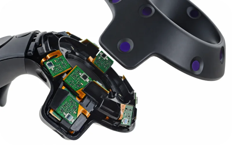

A VR motion controller PCB brings motion tracking, wireless communication, hand controls and haptic feedback into one compact electronic system. Most designs combine an inertial measurement unit (IMU), a microcontroller or radio, trigger and button inputs, an actuator and battery circuitry. Depending on the tracking technology, infrared emitters, photodiodes, capacitive grip sensors or camera modules may be mounted on separate boards or flex circuits around the housing. These are different manufacturing arrangements, not interchangeable versions of one standard VR controller board. In wearable haptic-glove circuit assemblies, sensor interconnects, actuator drive and flex handling add manufacturing requirements beyond those of a handheld controller.
Highleap Electronics provides PCB fabrication, approved component sourcing and SMT/THT assembly for custom electronic products, including VR controller mainboards, tracking sensor PCBAs and flexible interconnects. Through our electronic manufacturing services for OEM PCBAs, projects can be reviewed against the actual Gerber or ODB++ package, BOM, component placement data and required inspections. Board technology, programming and test operations are defined by the released design and quotation scope.
VR Motion Controller PCBs: Mainboards, Tracking Rings and Sensor Boards
The main PCB usually houses the controller processor, motion sensor interface, wireless circuit and power management. Additional boards depend on the physical controls and tracking architecture. A headset-tracked design may place infrared LEDs around a ring or shell; a base-station-tracked design can use distributed light sensors. Other products use a small trigger PCB, a grip-sensing flex or a separate charging-contact assembly.
For custom VR controller PCB manufacturing, those board types translate into distinct fabrication files, copper and stack-up requirements, assembly drawings and component populations. A sensor ring made from several small rigid boards needs different panelization and interconnections from an integrated rigid-flex structure. A compact wireless mainboard with fine-pitch packages may also require a different SMT inspection plan from a simple switch or contact board.
Define a board set that can actually be produced
Each PCB or PCBA should have a released part number and revision, even if left- and right-hand controllers share components. The assembly package identifies which boards receive an IMU, optical devices, connectors, actuators or mechanical contacts. That prevents the mainboard BOM from being mistaken for a complete controller electronics set and allows fabrication, purchased materials and subassemblies to be priced accurately.
IMU and Optical Tracking PCB Assembly for VR Controllers
An IMU sensor PCB assembly is defined by more than selecting a suitable accelerometer and gyroscope. Sensor axes, package orientation and the position of the assembled board relative to the controller shell must match the released coordinate system. SMT placement can verify pin-one orientation and package seating; a reference fixture can establish the installed direction of the sensor board where required.
Optical tracking brings different details to manufacturing. Infrared emitters need the specified polarity, orientation and optical clearance. Photodiodes and other light sensors may occupy multiple faces of the enclosure, making their board positions and connector maps important. Camera-based designs involve a different module and processing architecture and should only be included when the OEM design calls for them.
Keep tracking hardware checks separate from tracking performance
A fixture may confirm sensor identification, IMU response along defined axes, LED activation or photodiode electrical output. These checks help establish that the VR tracking sensor PCBA was populated and connected correctly. Full 6DoF pose accuracy, camera tracking algorithms and headset compatibility depend on the finished system, its calibration procedure and software.
Flexible and Rigid-Flex PCB Assembly for VR Controller Housings
Curved grips and tracking rings often leave limited room for conventional board-to-board connectors. VR controller flexible PCB manufacturing can provide connections to grip electrodes, infrared tracking elements and remote buttons while keeping the mainboard near the battery and radio. Other designs use separate rigid boards joined by a flex tail or a complete rigid-flex PCB construction.
The manufacturing drawing should distinguish flex sections that are folded once during installation from sections that repeatedly bend with a trigger or moving mechanism. These are not equivalent reliability conditions. Finished thickness, bend region, stiffener placement, component clearance and FPC connector engagement must follow the released design. The flexible PCB assembly process is especially relevant to component placement on flexible sections and the handling of shaped assemblies.
For a first article, the populated flex should fit the intended support surface without forcing a component, solder joint or connector tail into the bend. Where optical components are mounted on a curved structure, installation height and viewing direction should be included in the mechanical acceptance criteria.
Trigger, Grip Sensor and Haptic Driver PCBA Manufacturing
A VR controller mainboard PCBA may read Hall-effect or optical triggers, analog thumbsticks, touch electrodes, grip-force sensors and conventional buttons. These inputs differ in their physical reference points: a Hall sensor is positioned relative to a moving magnet, while a capacitive grip electrode depends on the electrode shape and surrounding insulation. Joystick height, switch operating direction and mounting tabs also affect assembly fit.
Haptic feedback introduces a separate power and mechanical interface. An ERM motor or LRA uses a driver and operating profile suited to the specified actuator. Its connector, placement, polarity and mounting interface need to match the assembly drawing; the motor should not be substituted by footprint alone. High-current haptic events also influence local decoupling and return paths on battery-powered boards.
What is inspected on the assembled controller electronics?
Visual and electrical inspection can establish component placement, trigger-sensor communication, input-state changes and commanded haptic-driver operation. Mechanical travel, grip sensing and actuator feel can be assessed under customer-defined fixtures and limits when those operations are included. This distinction gives an OEM VR haptic controller PCBA a measurable manufacturing acceptance plan without treating tactile experience as an automatic SMT result.
Highleap Electronics • PCB Manufacturing & Assembly
One-Stop PCB & PCBA Service for Your Next Build
From VR controller mainboards and sensor circuits to other custom electronics, Highleap can review PCB fabrication, approved components and assembly in one quotation. Ask about international delivery, after-sales support and convenient payment arrangements for your order.
One-Stop PCB & PCBA
Worldwide Shipping Options
After-Sales Support
Flexible Payment Options
| Get My Quote | Discuss My Build |
Shipping arrangements, after-sales coverage and payment terms are confirmed for each order.
Wireless VR Controller PCB: RF, Battery and Charging Circuits
A wireless VR controller PCB integrates a radio and antenna near other components that can influence its operating environment: a battery, tracking electronics, charging contacts and the user’s hand. Bluetooth or proprietary 2.4 GHz links require the specified RF parts, approved antenna clearance, PCB reference structure and enclosure configuration. Related Bluetooth PCB manufacturing considerations apply where that wireless platform is used.
Rechargeable models may use a USB-C connector, contact dock or another approved charging arrangement; some controllers use replaceable cells instead. Charger ICs, battery protection, temperature sensing, contact polarity and mechanical retention follow the specific design. The relevant battery management PCB assembly requirements can help define the power-stage manufacturing controls without implying that every controller contains a dedicated BMS board.
During assembly, the approved wireless module, antenna matching components, battery connector and charging contacts should remain consistent with the released BOM. Electrical charging and radio communication checks can be specified at PCBA level, while final radiated performance and battery safety depend on the finished product and its required qualification program.
VR Motion Controller PCB Prototyping, SMT Assembly and Testing
A VR motion controller PCB prototype is most useful when it represents the intended component placement and mechanical references. Prototype builds may establish whether optical sensors face the correct openings, the IMU board sits in its approved orientation, flex tails fit their connectors and the trigger or charging-contact boards install without strain. Those findings can be incorporated into the released PCB and assembly revisions before larger orders.
From first article to repeat PCBA production
For VR motion controller SMT assembly, the inspection plan follows the actual packages: miniature MEMS devices, radio ICs, connectors, sensor LEDs and any bottom-terminated components. Where required, an agreed PCBA first-article inspection can preserve component orientation, flex mating and mechanical references for repeat production. Left- and right-hand variants may share copper designs but require different approved BOMs or firmware identities.
Production PCB assembly functional testing can include sensor identification, buttons and analog inputs, haptic commands, battery and charger checks, optical emitter activation and defined wireless communication, subject to the supplied firmware and fixtures. Full tracking accuracy, gesture-recognition algorithms and VR-platform certification are separate product-level validations.
For a VR motion controller PCB manufacturing and assembly quote, supply Gerber/ODB++ data, stack-up, approved BOM, pick-and-place and assembly drawings, flex and enclosure details, tracking architecture, firmware or programming requirements, test procedures and quantities by variant. Highleap’s turnkey PCB assembly service can coordinate approved board fabrication, component purchasing and PCBA production. Specialized optical calibration, enclosure integration and other operations are included only when defined in the agreed scope.

Recommended Posts
Optical Transceiver PCB Assembly Services in China
Highleap Electronics provides optical transceiver PCB...
Precision Press Fit PCB Manufacturing with Tight Tolerances
Press-fit PCB manufacturing requires close coordination...
8 Layer HDI PCB Manufacturer in China
Highleap Electronics provides 8 layer HDI PCB...
8 Layer Rigid-Flex PCB Manufacturing and Cost Guide
An 8 layer rigid-flex PCB combines multilayer rigid...
How to get a quote for PCBs
Let’s run DFM/DFA analysis for you and get back to you with a report. You can upload your files securely through our website. We require the following information in order to give you a quote:
-
- Gerber, ODB++, or .pcb, spec.
- BOM list if you require assembly
- Quantity
- Turn time
For PCBA services, please provide your BOM (Bill of Materials) and any specific assembly instructions. We also offer DFM/DFA analysis to optimize your designs for manufacturability and assembly, ensuring a smooth production process.