
Motion Gaming Camera PCB Manufacturing & PCBA for Gesture, Player and Depth-Tracking Systems

Highleap Electronics manufactures customer-released motion gaming camera PCB assemblies for interactive vision systems. Production focuses on the optical stack, high-speed data path, illumination, calibration, enclosure cleanliness and repeatable reference-target testing.
Motion Gaming Camera PCB Manufacturing Is an Optical-Electronic Integration Problem
A motion gaming camera is not the same product category as a generic motion-detection CCTV camera. Gaming and interactive systems may use RGB imaging, infrared illumination, stereo cameras, structured-light or time-of-flight modules, IMUs and high-speed host links to observe player movement or gestures. Highleap Electronics manufactures customer-released motion gaming camera PCB and PCBA assemblies, so production must follow the actual sensor, optics, illumination, processor/interface and calibration architecture supplied by the OEM.
RGB gesture camera
Image sensor, lens, USB/high-speed interface and enclosure window dominate manufacturing alignment.
IR-assisted tracking camera
IR emitter boards, filters and camera sensitivity add optical-channel checks.
Stereo motion camera
Two sensor/lens channels require controlled baseline, orientation and paired calibration.
Depth-sensing module
Depth sensor or illumination module may contain supplier calibration that must remain matched to the host board.
Camera + IMU tracker
Sensor orientation, clocking and firmware identity matter for fusion systems.
Multi-camera gaming bar
Several cameras or emitters on one long mechanical assembly create board-to-board and alignment tolerances.
Sensor, Lens and Window Tolerances Stack Up in the Finished Camera
The active image comes from a mechanical stack: image sensor package, PCB datum, lens holder, lens focus, filter, enclosure window and mounting screws. A camera board can pass electrical inspection but produce a shifted, soft or partially blocked image after final assembly. First-article builds should therefore include the real lens, window and bracket.
| Optical item | Manufacturing risk | Useful pilot check |
|---|---|---|
| Image sensor | Rotation, contamination, wrong revision | Inspect orientation and capture reference image. |
| Lens holder/module | Tilt, focus shift, adhesive/torque variation | Use OEM focus/alignment procedure. |
| IR filter/window | Wrong material, scratches, film or dust | Controlled part, cleaning and final visual/capture check. |
| Stereo pair | Baseline or yaw/pitch mismatch | Fixture-controlled mechanical datum plus supplied calibration. |
| Emitter board | Wrong angle or channel population | Exercise every channel with approved optical target. |
Boards built around image sensors can be coordinated with camera PCB manufacturing, while compact sensor placement may use camera FPC or rigid-flex interconnects when the OEM needs a narrow optical head.
High-Speed Interfaces Need Signal Integrity and Mechanical Connector Control
Motion cameras can move substantial image data. Depending on architecture, the sensor may use MIPI-style interfaces internally while the finished module exposes USB or another high-speed host link. Manufacturing should preserve impedance-controlled routing, connector seating, shield/ground strategy and the approved cable. If the released design uses USB-C, connector shell anchoring and protection can follow USB-C connector assembly controls.
A cable that works on an open bench can become intermittent when routed tightly around the camera bar or enclosure. First-article testing should use the production cable length and final strain relief, not an engineering lab cable.
IR Illumination and Sensor Power Should Be Tested in Real Capture Modes
Infrared emitters and image processors can create switching loads and thermal concentration. Production should run the camera in the customer-defined capture mode while checking image stability, communication and any emitter channels. The released filter, driver and grounding arrangement should be preserved under EMI/EMC controls so clock or driver noise is not “fixed” by uncontrolled component changes.
Highleap Electronics • PCB Manufacturing & PCBA
Send the released PCB files, BOM, sensor/lens data, optical and enclosure drawings, firmware, calibration procedure, reference target, interface cables and production-test limits.
Request a Motion Gaming Camera PCB Quote →Discuss Your PCBA Build →
✓ DFM and DFA review✓ Prototype to repeat production✓ PCB fabrication and assembly
Calibration Must Be Defined by the OEM, Not Invented at the Factory
A motion-tracking camera may require focus, lens shading, stereo alignment, depth calibration, sensor offset or IMU alignment. Those procedures are product-specific. Highleap can execute supplied calibration software, fixtures and pass/fail limits, but should not infer tracking accuracy from the camera type.
The factory can confirm sensor communication, reference-image quality, emitter response, programmed calibration data and host transfer. Gesture recognition quality, skeletal tracking, depth accuracy and game-engine behavior are system-level outcomes unless the OEM supplies a validated production criterion.
Contamination Control Matters Because the Customer Sees the Optical Defect
Dust, fingerprints, flux residue or protective film can cause optical failures long after the PCBA itself passes AOI. Work instructions should define when the image sensor or lens is exposed, where cleaning is allowed, which protective films stay on during assembly and when the final window is inspected. Cosmetic handling becomes part of yield because a speck inside the sealed optical stack can force complete rework.
Where a finished camera module is assembled at Highleap, the scope can extend from PCB assembly into box build with customer-defined optical cleanliness and packing requirements.
Motion Gaming Camera PCBA for US and European XR Developers
A US or Canadian XR team sourcing motion gaming camera PCB assembly in China should provide the actual optical stack and calibration flow, not only a sensor part number. German and French machine-vision or immersive-game developers often work with precise brackets and industrial enclosures, so CAD datums and cable routing should be included in the release package. UK and Dutch teams using stereo or depth modules should identify which calibration data are unique to each camera pair. Italian and Spanish interactive-installation companies can avoid field problems by freezing the enclosure geometry that may sit close to IR emitters or camera windows.
Critical image sensors, lenses, oscillators, memory and high-speed connectors should stay under approved component sourcing. A footprint-compatible sensor or lens is not automatically calibration-compatible.
NPI and End-of-Line Test for Motion Gaming Cameras
- Inspect optical PCBA: confirm sensor orientation, connector seating, lens hardware and emitter population.
- Program: load approved firmware and read back sensor/module identities.
- Capture: acquire the customer reference target through every required imaging channel.
- Illumination: exercise each IR or auxiliary emitter state and verify expected camera response.
- Calibration: run supplied focus/stereo/depth/IMU routines where required.
- Host transfer: move image data through the production cable and customer host utility.
- Final enclosure: repeat critical capture after window, bezel and mechanical screws are installed.
Highleap can build this sequence around functional testing and use DFT points for rails, reset, sensor buses and programming without opening the calibrated optical stack for routine debug.
Camera Module Revision Control Is Critical to Calibration Repeatability
Image sensors, lens modules and depth-camera subassemblies can change revision while keeping a similar connector or mechanical envelope. A replacement module may contain different onboard firmware, calibration memory or optical characteristics. The BOM and first-article record should therefore capture the exact module revision, not just a generic family name.
Rework also needs a calibration rule. Replacing a lens, sensor board, stereo partner, emitter board or main processor may invalidate stored alignment data. The OEM should define which replacements require recalibration and whether calibration data are tied to a serial number. This prevents a repaired camera from passing USB communication while carrying an optical offset that appears only in the final gaming application.
RFQ Inputs for Motion Gaming Camera PCB Production
Provide Gerber/ODB++, stack-up, BOM, centroid, assembly drawing, image-sensor and lens/module datasheets, optical and enclosure CAD, FPC/cable drawings, firmware, calibration software/data rules, reference targets, host utility, pass/fail limits and quantity by camera variant. A first article inspection should freeze sensor, lens, window, bracket and cable relationships before volume production.

Recommended Posts

How to Reduce PCB Costs in 2026
Table of contents Why 80% of PCB Cost Is Locked in at...
10 Layer PCB Cost Drivers for Materials, HDI and Testing
Figure 1. 10 layer PCB cost drivers for materials HDI and...
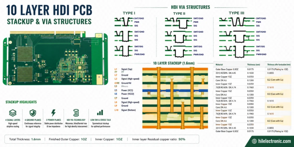
10 Layer HDI PCB Engineering for Microvias and BGA Escape
Figure 1. 10 layer HDI PCB engineering for microvias and...

8 Steps to Manufacture a Perfect Aluminum PCB
Figure 1. Aluminum Pcb manufacturing reference for PCB...
How to get a quote for PCBs
Let’s run DFM/DFA analysis for you and get back to you with a report. You can upload your files securely through our website. We require the following information in order to give you a quote:
-
- Gerber, ODB++, or .pcb, spec.
- BOM list if you require assembly
- Quantity
- Turn time
For PCBA services, please provide your BOM (Bill of Materials) and any specific assembly instructions. We also offer DFM/DFA analysis to optimize your designs for manufacturability and assembly, ensuring a smooth production process.