
RT duroid 6006 PCB Manufacturing
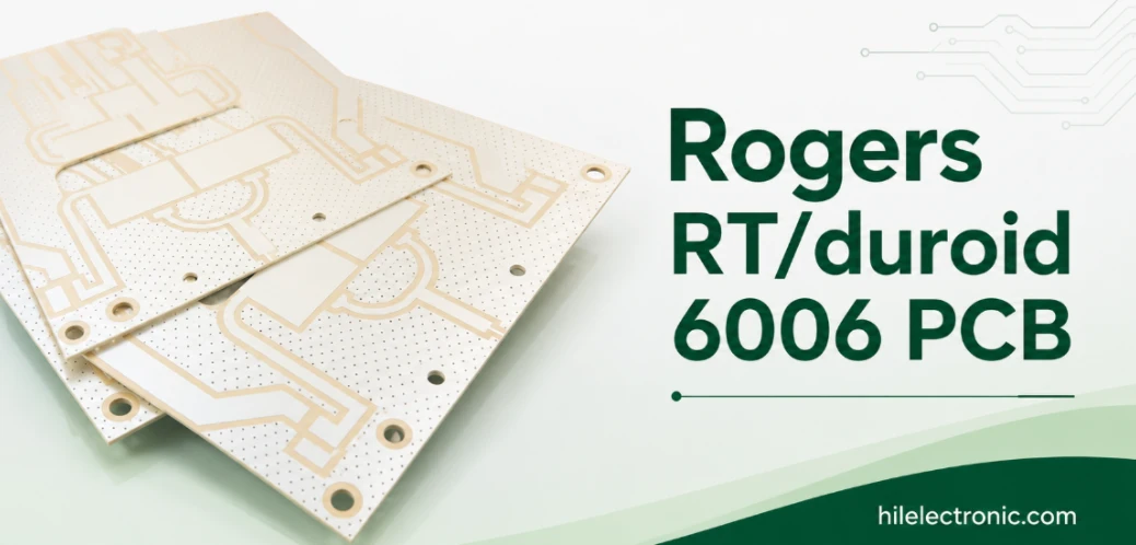
RT duroid 6006 PCB manufacturing is mainly a high-Dk geometry problem. The material can support compact microwave structures, but the finished dielectric thickness and conductor dimensions must stay within the tolerance assumed by the RF design. RT/duroid 6006 is selected when circuit area is expensive. Its high dielectric constant can shorten filters, resonators, patch antennas and amplifier matching networks, but the smaller geometry brings tighter tolerance and stronger temperature sensitivity. The useful question is therefore not whether the material is “higher performance,” but whether the footprint reduction is worth the tuning and process burden. If a higher dielectric constant is needed, 6010.2LM boards for stronger RF miniaturization require redesigned electrical dimensions and a new tolerance review.
Highleap Electronics manufactures PCBs using RT/duroid 6006 from engineering prototypes through repeat production, with PTFE-compatible drilling, controlled copper, critical-dimension inspection and optional module assembly.
RT/duroid 6006 is addressed here through compact high-Dk microwave fabrication. The manufacturing route must preserve the intended dielectric geometry and conductor dimensions while controlling drilling, registration and inspection for the finished board.
When High-Dk PCB Materials Are a Better Choice
High-Dk materials are appropriate when the enclosure, antenna aperture or RF module footprint cannot accommodate a lower-Dk circuit. They can reduce guided wavelength and distributed-element size. They are less attractive when bandwidth, temperature stability or broad manufacturing tolerance matters more than area. When reviewing RO3006 fabrication as a separate laminate route, compare the actual construction and manufacturing constraints rather than matching only nominal Dk.
The temperature tradeoff
RT/duroid 6006 has a relatively large thermal coefficient of dielectric constant. Narrowband filters, patch antennas and phase-sensitive circuits should be modeled and tested across the intended temperature range. Self-heating in an amplifier can also shift the matching network, so hot-state measurements may be more meaningful than room-temperature tuning alone.
| Design objective | Benefit from 6006 | Penalty to manage |
|---|---|---|
| Smaller resonator | Reduced electrical length | Higher percentage sensitivity to line and gap error |
| Compact patch antenna | Reduced radiator size | Potential bandwidth and temperature shift |
| Dense PA matching | Shorter stubs and transformers | Self-heating and tuning sensitivity |
| Restricted X-band module | More RF function within the enclosure | Tighter machining and housing correlation |
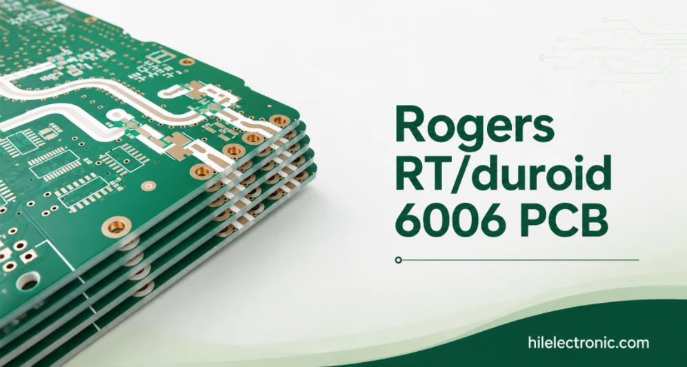
Material scope: the Rogers product name is used to identify the laminate specified for the PCB build. Highleap Electronics provides PCB fabrication and assembly, while the laminate is sourced and verified separately.
Turning a 6006 Model Into Manufacturable Geometry
The model should identify the Dk source, nominal and finished thickness, copper foil, plating and surface finish. High Dk compresses line widths and gaps, so finished geometry should be used for acceptance. A generic artwork tolerance may be too loose for the frequency-setting dimensions.
PTFE processing and hole reliability
6006 still requires a PTFE-compatible hole preparation and plating route. The drill plan, activation, copper deposition and finished plating must be reviewed against hole size and board thickness. Mechanical features should be supported so the substrate does not distort during routing or assembly.
- Identify the dimensions that set resonance or coupling.
- Include final plating and finish in the geometry model.
- Define temperature-test points before prototype tuning.
- Lock copper foil and laminate thickness to the released simulation.
- Review PTFE activation and plated-hole evidence.
- Use common RF and housing datums for compact modules.
For additional context, see miniaturization techniques in RF PCB.
Prototype Tuning Without Creating a Production Trap
Tuning is useful only when it can be converted into a controlled artwork or assembly change. A prototype that requires hand adjustment on every unit is not ready for volume. Highleap can provide critical-dimension records and retain the approved artwork revision so the customer can correlate tuning changes with the built board.
Where 6006 fits best
The material is strongest in compact microwave filters, antennas, radar subcircuits and amplifier modules with limited area and an acceptable temperature-control plan. If frequency stability is the dominant requirement, a different high-Dk thermoset material may be preferable even if the board becomes slightly larger.
Comparison should be application-driven
6006, RO3006, TMM6 and 6010-class materials differ in temperature behavior, process route, available construction and mechanical properties. A substitution should should not be approved from nominal Dk alone.
From Compact Prototype to Repeat Production
The production release should contain the exact material and copper, finished thickness, critical dimensions, temperature range, housing interface, finish, drill plan and test method. Highleap can support prototypes, low-volume production and optional assembly, with lead time confirmed after material availability and the PTFE route are reviewed. Highleap reviews line width, spacing, vias, lamination and drilling against the compact construction. For filter or resonant designs, the manufacturing drawing should identify the dimensions that need recorded first-article evidence. Exact material property values should be checked against the current supplier documentation for the specified grade and construction.
Share the 6006 layout, target frequency, temperature range and housing constraints. Highleap will review whether the miniaturized geometry can be etched, plated, assembled and repeated without relying on uncontrolled hand tuning.
6006 design questions
Does high Dk mean lower loss? No. Dk primarily changes geometry; loss and temperature behavior are separate properties.
Can 6006 replace another Dk 6 material directly? Not without reviewing design Dk, thickness, TCDk, copper and fabrication route. For quotation, include the material grade, finished thickness, copper, critical RF dimensions and quantity. If tuning or RF measurement is required, define the method before fabrication so the prototype scope is clear.

Recommended Posts

TMM4 Filter PCB Manufacturing
TMM4 filter PCB manufacturing is controlled by the...

TMM3 PCB Manufacturing for RF Modules
TMM3 PCB manufacturing is most useful where the RF module...

TMM6 PCB Fabrication
TMM6 fabrication is the process-control page for a mid-Dk...

TMM10 PCB Manufacturing for Compact RF Designs
Table of contentsHow TMM10 Shrinks RF StructuresTMM10 vs...
How to get a quote for PCBs
Let’s run DFM/DFA analysis for you and get back to you with a report. You can upload your files securely through our website. We require the following information in order to give you a quote:
-
- Gerber, ODB++, or .pcb, spec.
- BOM list if you require assembly
- Quantity
- Turn time
For PCBA services, please provide your BOM (Bill of Materials) and any specific assembly instructions. We also offer DFM/DFA analysis to optimize your designs for manufacturability and assembly, ensuring a smooth production process.