
TMM3 PCB Manufacturing for RF Modules

TMM3 PCB manufacturing is most useful where the RF module also has mechanical or machining constraints. In these designs, a stable mechanical interface can be as important as maximum dielectric performance. TMM3 is selected when an RF circuit must behave as part of a mechanical module. The board may include machined cavities, mounting holes, plated edges, wire-bond pads, clamps or a metal housing. In that environment, low loss is only one requirement; rigidity, dimensional accuracy, plated-hole reliability and surface condition are equally important.
Highleap Electronics supports TMM3 PCB fabrication for microwave modules, including precision routing, plated holes, cavity features, selective finishes and optional wire-bond or component assembly. The manufacturing plan is built around the module architecture rather than a generic laminate checklist.
TMM3 is addressed through mechanically integrated RF modules. Cavities, connector edges, plated holes, mounting references and RF traces need a common datum and should be checked together when the board interfaces directly with a mechanical enclosure.
Why TMM3 Fits Mechanical RF Module PCB Designs
TMM3 has a relatively low dielectric constant within the TMM family, which supports wider transmission lines and larger coupling gaps. Wider geometry can improve etch tolerance and broadband behavior when the module has enough area. The thermoset ceramic-filled structure also resists the cold flow associated with softer PTFE laminates, making it suitable for assemblies that use screws, clamps or wire bonds.
When mechanical stability matters more than maximum miniaturization
| Module requirement | Why TMM3 may fit | What still requires control |
|---|---|---|
| Wire-bond pads | Rigid support under bond force and heat | Finish, cleanliness, pad planarity and bond recipe |
| Machined cavities | Thermoset construction supports stable routing | Datum, edge quality and cavity-to-circuit alignment |
| Plated mounting holes | Mechanical and thermal stability support interconnect reliability | Drill, plating, torque and local copper design |
| Broadband RF lines | Lower Dk gives wider, less concentrated geometry | Copper profile, thickness and launch design |
TMM3 is less attractive when the product requires extreme miniaturization. In that case, TMM4, TMM6 or a higher-Dk substrate may reduce circuit area, but the geometry and tolerance budget must be revisited.
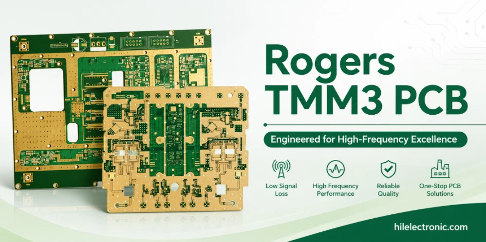
Material scope: Highleap Electronics is the PCB manufacturer and assembler for the build described here. Rogers and the referenced grade names identify the specified material and are not a description of Highleap material manufacturing.
Machining, Cavities and Plated Holes on TMM3
Mechanical RF modules should be released from a common datum system. The cavity, RF traces, plated holes, connector edge and housing features must align after routing and finish. Highleap reviews routing tools, support method, edge tolerances and plating sequence before fabrication. Small mechanical features should not be specified only from the nominal CAD outline; finished dimensions and inspection points need to be identified. Highleap reviews cavities, machined areas, plated holes, mounting features and RF layers together. The fabrication drawing should identify the dimensions that control both mechanical fit and electrical geometry so they are inspected under one revision. Exact material property values should be checked against the current supplier documentation for the specified grade and construction.
Plated holes and wire-bond finishes
Through holes may provide grounding, connector attachment or mechanical retention. Their reliability depends on hole preparation, plating thickness and the stress applied during assembly. Wire-bond pads add another layer of control: the selected finish must be compatible with the wire and bonding process, and contamination or excessive finish variation can reduce bond yield.
- Use common datums for RF artwork, machined cavities and housing features.
- Mark holes that carry mechanical load separately from signal or ground vias.
- Define selective finish and mask keep-outs around bond pads and RF structures.
- Control routed edge quality where a launch or housing wall is close to the circuit.
- Verify flatness and local support before wire bonding.
- Retain microsection and dimensional data for qualified repeat builds.
Highleap’s PCB wire bonding guidance explains why pad metallurgy, cleanliness and substrate support must be considered with the bare-board design.
TMM3 Module Integration and Thermal Verification
The RF board does not operate in isolation. A metal lid, cavity wall, heat spreader, fastener or adhesive can load the field and change the response. Temperature also changes both the substrate and surrounding structure. Prototype validation should therefore use the intended housing or a representative fixture rather than testing only an open board.
Typical production use cases
TMM3 is a practical choice for amplifier modules, broadband couplers, antenna-feed assemblies, microwave test hardware and mechanically retained RF circuits. It may also be used where a PTFE alternative is desired but the module needs better resistance to creep or more predictable machining.
For products that combine the RF board with a metal structure, Highleap can review the design together with high-frequency PCB fabrication and assembly requirements. The review should include mounting torque, thermal interface, connector fit and any post-assembly tuning access.
Qualifying a TMM3 Prototype for Repeat Production
The qualification package should match the actual product risk. A module with wire bonds may require finish certification, bond-pull data or a customer-defined assembly test. A cavity filter may require critical-dimension reporting and S-parameter correlation. A mechanically clamped board may need flatness, hole-location and torque verification.
Highleap can supply bare-board prototypes, low-volume production and optional assembly. Payment terms, shipment method and delivery schedule are confirmed with the quotation after material availability and machining complexity are known. Repeat orders can use the approved construction and retained first-article data to reduce avoidable changes.
Provide the TMM3 artwork, mechanical drawing, housing interface, finish requirement and intended assembly method. Highleap will review the circuit and mechanical features as one production module.
TMM3 module questions
Is TMM3 processed exactly like FR-4? No. It is a rigid thermoset microwave material, but machining, drilling and finish still require material-specific controls. For quotation, include the mechanical drawing, stackup, machining requirements, copper, holes, finish and quantity. This lets the manufacturer price the machining and PCB work as one build.
Can TMM3 support wire bonding? Yes, when the finish, pad geometry, cleanliness and assembly process are defined.

Recommended Posts

TMM4 Filter PCB Manufacturing
TMM4 filter PCB manufacturing is controlled by the...

TMM6 PCB Fabrication
TMM6 fabrication is the process-control page for a mid-Dk...

TMM10 PCB Manufacturing for Compact RF Designs
Table of contentsHow TMM10 Shrinks RF StructuresTMM10 vs...

TMM10i PCB Fabrication and DFM
TMM10i PCB fabrication has a stronger DFM emphasis because...
How to get a quote for PCBs
Let’s run DFM/DFA analysis for you and get back to you with a report. You can upload your files securely through our website. We require the following information in order to give you a quote:
-
- Gerber, ODB++, or .pcb, spec.
- BOM list if you require assembly
- Quantity
- Turn time
For PCBA services, please provide your BOM (Bill of Materials) and any specific assembly instructions. We also offer DFM/DFA analysis to optimize your designs for manufacturability and assembly, ensuring a smooth production process.