
USB Audio Interface PCB Manufacturing & Assembly for Professional Audio Products
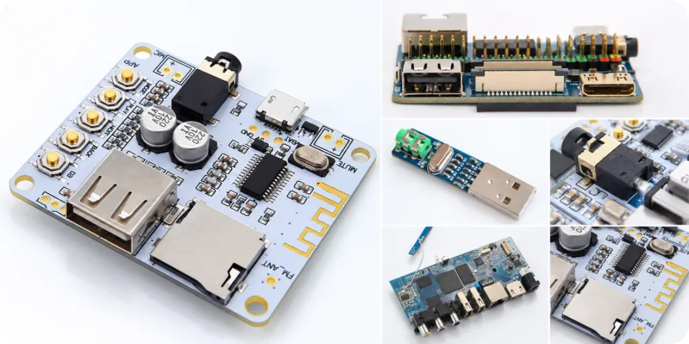

A USB audio interface can be recognized by a computer and still fail the test that matters to its user: clean recording and dependable playback. A noisy microphone input, reversed monitor channel or poorly seated front-panel connector may not appear during a basic USB connection check. Those are also the details that make USB audio interface PCB manufacturing different from simply populating a digital control board. For karaoke mixing-console board assembly, microphone gain stages, mixing controls and audio outputs should be checked together for grounding, connector placement and test access.
Highleap Electronics manufactures bare PCBs and assembles PCBAs for customer-designed electronics across multiple industries. USB audio interfaces are one of the applications we can review for fabrication and assembly. We do not sell a standard finished audio interface through this page. The objective is to help an OEM or hardware purchasing team understand what should be specified, preserved and tested when its own audio circuit moves into production.
Where a USB Audio Interface PCB Gains or Loses Audio Quality
The signal path depends on the product. A recording interface may take a microphone or instrument signal through an analog front end and an ADC before sending digital audio over USB. A playback device may take USB audio through a DAC and then drive a line output or headphone amplifier. A two-input studio interface can contain both paths, along with monitoring controls. These differences determine which components and production checks are critical.
Keep the input stage consistent
Microphone and high-impedance instrument inputs are sensitive to the way the approved circuit is assembled. Amplifiers, references, gain-setting resistors, coupling parts and filters should follow the released BOM. Where the design provides phantom power, its switching, protection and voltage-rated parts require their own defined checks. A component with the same package and nominal value is not automatically an acceptable substitute in a noise-sensitive stage.
Do not redesign the return path during manufacturing
Digital clocks, USB signals, converters and analog circuitry may share a small board. The correct grounding and power-distribution strategy belongs to the OEM’s electrical design; there is no universal rule that every audio PCB needs a split ground plane. Fabrication changes affecting copper geometry, reference planes, filtering or component position should be reviewed rather than treated as routine process optimizations.
For a finished unit, the relevant questions are audible and measurable: Does each input reach the correct channel? Is the gain behavior as specified? Do the outputs meet the OEM’s noise, level and distortion limits? The factory can test against defined limits, but the published audio-performance specification must come from validated product requirements.
Connectors, Controls and the Reality of Assembly
USB audio interface boards often mix fine-pitch ICs with physically large connectors and user controls. XLR or combo jacks, TRS sockets, encoders and potentiometers can make mechanical alignment as important as solder placement. A PCBA may pass an electrical test yet be difficult to install if its connectors do not line up with the front or rear panel.
Three details worth confirming before the first build
- Connector fit and support: define mounting-hole dimensions, panel datums and any mechanical retention needed for parts exposed to repeated cable insertion.
- USB connection and power: specify the actual USB connector, data implementation and power arrangement. A USB-C receptacle alone does not mean the product supports USB 3 or USB Power Delivery.
- Controls and channel mapping: document the expected orientation and operation of gain knobs, buttons, monitor controls and left/right outputs.
If one enclosure has several board variants, a first-article fit check can reveal problems before a larger assembly order is released. This is especially useful for compact interfaces whose jacks are mechanically tied to both the PCB and a metal enclosure.
What Highleap Manufactures for Customer-Designed Audio Electronics
Highleap is a PCB manufacturing and assembly factory, not a manufacturer limited to USB audio products. Our broader electronic manufacturing services serve customer-owned electronics in different applications. An audio project is quoted according to its actual board construction, parts, assembly process and requested deliverables.
A bare-PCB order concerns the fabrication data, materials, layer stack-up, drill and outline requirements. A populated-board order adds component supply arrangements and circuit board assembly work. Many audio products combine surface-mount semiconductors and passives with through-hole or mechanically reinforced connectors, so both processes may need to be specified. Programming, configuration, specialized inspection and functional test are separately defined according to the project.
Which changes need approval?
The most important production decisions are often the ones a purchasing or process team might otherwise consider minor. Changing an op-amp, converter reference, oscillator, USB controller or connector can affect noise performance, firmware compatibility or enclosure fit. A design-for-assembly (DFA) review can identify placement, connector and process concerns, while changes to the customer’s electrical design still require approval.
Equally, board-level work should not be confused with a complete audio product. Host-driver behavior, enclosure grounding, final EMC compliance and published end-product audio performance require appropriate system-level validation. Any work beyond PCB fabrication and assembly should be explicit in the quotation rather than implied by the phrase “turnkey.”
Testing the Actual Audio Paths Before Production Release
USB enumeration is a useful first check, but it does not show that every analog input, monitor control or output works. When selecting PCB and PCBA testing methods, the OEM-defined production procedure should reflect the channels and features actually fitted to the board.
For example, a customer-approved test plan may call for:
- Device identification and firmware or configuration verification on a defined host setup.
- A known audio signal applied to each specified input, with the resulting channel and level checked.
- Left/right line or headphone output checks using defined loads and signal levels.
- Operation of gain, mute, monitor, buttons, encoders or phantom-power functions, where present.
- Measurements such as frequency response, noise or THD+N only when the OEM provides limits, equipment requirements and a repeatable method.
A multi-channel product needs an explicit channel map; a simple stereo loopback does not verify unrelated channels. Reworked converters, jacks or analog components may also require a targeted retest. Clear limits make results useful for acceptance and repeat orders instead of leaving “audio tested” as an undefined promise.
What to include in the RFQ
To compare PCB and PCBA quotations fairly, supply the Gerber or ODB++ files, stack-up, assembly drawings, pick-and-place data and an approved BOM. For an audio build, also include the connector-to-enclosure dimensions, firmware or configuration files where applicable, an input/output channel map, the requested test method and quantities by board variant. Identify any components that must not be substituted. Highleap’s PCB assembly file requirements provide a useful reference for organizing the core production package.
Highleap Electronics can review those documents to establish a clear manufacturing scope for your USB audio interface PCB—or for another customer-designed electronic board. A useful quotation separates fabrication, material sourcing, assembly, programming and testing so you can see exactly what is included before placing an order.

Recommended Posts

TMM4 Filter PCB Manufacturing
TMM4 filter PCB manufacturing is controlled by the...

TMM3 PCB Manufacturing for RF Modules
TMM3 PCB manufacturing is most useful where the RF module...

TMM6 PCB Fabrication
TMM6 fabrication is the process-control page for a mid-Dk...

TMM10 PCB Manufacturing for Compact RF Designs
Table of contentsHow TMM10 Shrinks RF StructuresTMM10 vs...
How to get a quote for PCBs
Let’s run DFM/DFA analysis for you and get back to you with a report. You can upload your files securely through our website. We require the following information in order to give you a quote:
-
- Gerber, ODB++, or .pcb, spec.
- BOM list if you require assembly
- Quantity
- Turn time
For PCBA services, please provide your BOM (Bill of Materials) and any specific assembly instructions. We also offer DFM/DFA analysis to optimize your designs for manufacturability and assembly, ensuring a smooth production process.