
2-in-1 Laptop PCB and PCBA Manufacturing for Convertible and Detachable Designs
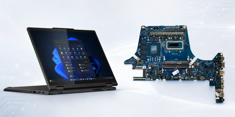
Table of contents
- Separate Convertible and Detachable Electronics Before Manufacturing
- Hinge FPC and Rigid-Flex Interconnects Need Dedicated DFM
- Mainboard Fabrication and BGA Assembly Still Follow Laptop-Class Density
- Touch, Display, Camera and Sensor Interfaces Expand the Test Map
- Assembly Handling for Fine-Pitch Flex Connectors and Moving Interconnects
- Control Mainboard, Base, Battery and Flex Revisions as One Product Set
- NPI, Flex-Life Risk and Cost Drivers for 2-in-1 Electronics
- International Supply Support for Convertible and Detachable Electronics
- Run a Manufacturing Review Before Rigid and Flex Tooling
A 2-in-1 computer combines laptop-class processing with a mechanical architecture that changes how the motherboard connects to the display, touch system, cameras, sensors, keyboard base and battery. In a convertible design, interconnects repeatedly move through a hinge; in a detachable design, computing electronics may be concentrated in the tablet section with a separate base or keyboard PCB.
Highleap Electronics supports customer-owned 2-in-1 electronics from released rigid PCB, flex PCB or rigid-flex data through fabrication, PCBA assembly, approved sourcing and customer-defined functional testing. The customer remains responsible for the hinge architecture, flex life requirement, device safety, firmware and complete product qualification.
The manufacturing plan should treat the rigid motherboard and moving interconnects as one released electronics system. A robust mainboard cannot compensate for a flex cable with an undefined bend zone, and a well-designed hinge cannot correct a mismatched connector or revision.
1. Separate Convertible and Detachable Electronics Before Manufacturing
Many convertible notebooks keep the primary motherboard in the base while display, camera, antenna and touch connections pass through a rotating hinge. Detachable products may place the main compute board behind the display and use a simpler keyboard/base PCBA connected through a docking or board-to-board interface. These architectures create different PCB sets and different manufacturing risks.
Factory Dependencies
The RFQ should therefore identify every board and flex assembly included in the product: mainboard, daughterboards, hinge FPC, keyboard/touchpad board, battery interconnect and any docking interface. The revision relationship between those items should be explicit before material is purchased.
2. Hinge FPC and Rigid-Flex Interconnects Need Dedicated DFM
A flex circuit that moves through a hinge is both an electrical interconnect and a mechanical fatigue element. Its copper geometry, bend direction, layer construction, stiffeners, coverlay openings and connector transition should follow the customer’s released design and bend-life requirement.
Flex Construction
Highleap can review flex PCB manufacturing and rigid-flex PCB data where used. The manufacturing review should confirm that bend zones are clearly identified, stiffeners do not enter the moving region, connectors have adequate support and panelization does not introduce handling damage.
Connector Transition
Manufacturing can control the flex construction and workmanship, but hinge life must be validated in the finished mechanical assembly under the customer’s specified motion, bend radius and environmental conditions.
Translate the Hinge Geometry Into Manufacturable Flex Data
The flex manufacturer needs released electrical and mechanical information, not only a note that the circuit passes through a hinge. The fabrication package should identify the rigid and flexible zones, copper construction, coverlay openings, stiffeners, connector lands, finished outline and any controlled-impedance requirement. The product team should separately define the installed bend path and motion envelope used for system qualification.
- Neutral bend behavior: copper and dielectric construction should follow the approved flex design so the manufacturer does not alter the mechanical behavior to solve a fabrication issue without review.
- Rigid-to-flex transitions: pad geometry, stiffener edges and coverlay openings need DFM attention because concentrated strain or poor solder access can create failures outside the main dynamic bend zone.
- Connector datum: flex length and connector position should be checked against the hinge and enclosure drawings, particularly where very little service loop is available.
- Assembly protection: work instructions should prevent creasing, excessive folding or forced connector insertion while the flex set is being installed into a partially assembled product.
Prototype Flex Success Does Not Automatically Prove Production Readiness
Early samples can function correctly even when the production process still lacks a controlled bend fixture, cable-routing instruction, strain-relief method or acceptance rule for cosmetic marks. During NPI, the team should capture how the flex is packed, handled, installed and inspected in addition to validating the electrical circuit itself. Those controls become more important when multiple flex circuits, antennas or display cables share the same hinge volume.
If the program requires mechanical cycling or other flex-life qualification, the cycle count, motion profile, fixture and pass/fail criteria should come from the customer’s product requirement. Highleap can manufacture the released flex or rigid-flex assembly and execute agreed production checks, but the final durability requirement remains a system-level engineering decision.
3. Mainboard Fabrication and BGA Assembly Still Follow Laptop-Class Density
The 2-in-1 form factor does not remove the normal laptop motherboard challenges. Processor/SoC, memory, storage, wireless, power conversion and high-speed display/data interfaces can still demand a dense multilayer or HDI design.
SMT Control
Where the layout uses microvias or blind vias, Highleap can review the released build through HDI PCB manufacturing. Where a conventional multilayer structure is sufficient, there is no manufacturing benefit in forcing HDI solely because the product is convertible.
Connector / Secondary Assembly
On assembly, BGA and fine-pitch packages can be supported with controlled printing, placement, reflow, AOI and targeted X-ray as appropriate. The mainboard plan should also account for low-profile connectors and underside components that interact with the thin mechanical stack.
Highleap Electronics • PCB Manufacturing & PCBA
Request a 2-in-1 Laptop PCB and Flex Review
Send your Gerber or ODB++, BOM, assembly data and quantity. Highleap will review the PCB fabrication, sourcing, assembly, programming and test scope for a controlled build.
Request a PCB & PCBA Quote →Discuss Manufacturing Requirements →
✓ DFM and DFA review ✓ Prototype to repeat production ✓ PCB fabrication and assembly
4. Touch, Display, Camera and Sensor Interfaces Expand the Test Map
Convertible and detachable products often integrate touch displays, cameras, orientation sensors, microphones and other devices whose interfaces pass through flex cables or compact connectors. These functions create failure modes that may not appear during a simple motherboard boot test.
Connector Control
The customer test plan should identify which interfaces are verified at PCBA level and which require the assembled display or base. Highleap can execute functional testing from approved procedures, using production panels, golden peripherals or simulators where available.
Installation Risk
For detachable systems, the docking or base connection deserves its own acceptance step because charging, keyboard, touchpad, USB or other signals may pass through the interface. Mechanical wear qualification remains a system-level validation activity.
5. Assembly Handling for Fine-Pitch Flex Connectors and Moving Interconnects
Small FPC connectors and thin flex circuits can be damaged after a technically correct soldering process if latches are forced, cables are creased or the assembly is handled without support. Work instructions should define connector opening/closing, insertion depth, cable orientation and any temporary protection required during later operations.
Connector Transition
- Inspect connector body seating and latch condition after reflow.
- Use approved cable orientation and bend direction during pilot integration.
- Protect exposed flex contact areas from contamination and mechanical damage.
- Keep rework heat away from nearby plastic flex connectors unless a controlled method is approved.
- Confirm that adhesives, shields or mechanical retainers are included only when shown on the released assembly data.
6. Control Mainboard, Base, Battery and Flex Revisions as One Product Set
A 2-in-1 platform can fail configuration control even when every individual PCB is correctly documented. A mainboard revision may require a different hinge flex, a display supplier change may require another cable, or a base connector change may affect firmware and test.
Flex Construction
The production release should therefore map all electronics revisions into one product configuration. Highleap can support approved sourcing, but alternates that affect connector fit, display compatibility, battery/charging behavior or firmware should be returned for customer approval.
Connector Transition
| Configuration item | Control needed |
|---|---|
| Mainboard | PCB/BOM revision, firmware image and test profile. |
| Hinge flex or rigid-flex | Drawing revision, connector combination and bend-zone definition. |
| Display/touch module | Approved part number and mating cable/interface. |
| Keyboard/base board | Hardware revision and docking/base interface configuration. |
| Battery/power interconnect | Approved connector, polarity and system assembly instruction. |
7. NPI, Flex-Life Risk and Cost Drivers for 2-in-1 Electronics
Cost can come from the rigid motherboard, the moving interconnects and the integration process. HDI or rigid-flex structures, fine-pitch packages, double-sided SMT, flex stiffeners, special connectors, manual cable operations, programming and broad system-interface testing all add different types of manufacturing work.
Key Manufacturing Controls
- Flex Construction: The pilot build should prove flex-to-connector fit, assembly handling, hinge routing and the functional interface map before larger quantities are committed. It should not be used to declare hinge life or drop performance without the customer’s defined mechanical qualification test.
- Connector Transition: For repeat production, retain the accepted rigid PCB build, flex construction, BOM, assembly sequence, firmware and test records. That controlled set makes later design changes visible instead of allowing a new cable or display part to enter production informally.
8. International Supply Support for Convertible and Detachable Electronics
Convertible and detachable computers create a more complicated manufacturing boundary than a conventional notebook because the electronics may be distributed between display, base, keyboard, hinge and removable modules. Cross-border production is most reliable when the complete rigid/flex interconnect set is released as one controlled product configuration.
United States and Canada: Convertible Product Development
A team sourcing a 2-in-1 laptop PCB manufacturer in China should identify whether the project is a 360-degree convertible, a detachable tablet-and-keyboard system or another architecture. That decision affects board location, hinge interconnects, battery distribution, connector count and which PCBAs require programming and functional test.
Germany, the UK and France: Rigid-Flex and Mechanical Interface Control
For European projects, convertible laptop PCBA assembly often depends on FPC or rigid-flex interfaces that must match mechanical drawings and bend constraints. The factory should build to the released flex construction and stiffener/coverlay details, while the customer retains responsibility for the product’s motion envelope and flex-life qualification.
Japan, South Korea and Singapore: Compact Integration and Variant Management
For high-density portable hardware, a detachable computer PCB supplier may need to manufacture a mainboard, interface board and several flex circuits together. Linking those items to one revision set, approved BOM and test map reduces the risk that mechanically compatible parts from different revisions are mixed during integration.
Highleap can support international rigid PCB, flex/rigid-flex and PCBA production when the released data defines the interfaces. Include destination, quantities per board set, mechanical files and the expected assembly/test scope so the manufacturing review can identify cross-board dependencies before tooling.
9. Run a Manufacturing Review Before Rigid and Flex Tooling
Manufacturing Sequence
- Project Package. Send the rigid-board Gerber/ODB++, flex or rigid-flex fabrication data, BOM, CPL, assembly drawings, quantities and hardware revisions. Add the hinge/mechanical drawing, display/touch interface information, firmware and test procedure where relevant.
- Manufacturing Review. Highleap can review the PCB, flex and assembly package before tooling and provide a quotation for fabrication, sourcing, PCBA assembly, inspection and customer-defined testing. Submit the files through the PCB assembly quote page.

Recommended Posts

TMM4 Filter PCB Manufacturing
TMM4 filter PCB manufacturing is controlled by the...

TMM3 PCB Manufacturing for RF Modules
TMM3 PCB manufacturing is most useful where the RF module...

TMM6 PCB Fabrication
TMM6 fabrication is the process-control page for a mid-Dk...

TMM10 PCB Manufacturing for Compact RF Designs
Table of contentsHow TMM10 Shrinks RF StructuresTMM10 vs...
How to get a quote for PCBs
Let’s run DFM/DFA analysis for you and get back to you with a report. You can upload your files securely through our website. We require the following information in order to give you a quote:
-
- Gerber, ODB++, or .pcb, spec.
- BOM list if you require assembly
- Quantity
- Turn time
For PCBA services, please provide your BOM (Bill of Materials) and any specific assembly instructions. We also offer DFM/DFA analysis to optimize your designs for manufacturability and assembly, ensuring a smooth production process.