
Portable Air Quality Monitor PCB Manufacturing for PM, CO2 and VOC Devices
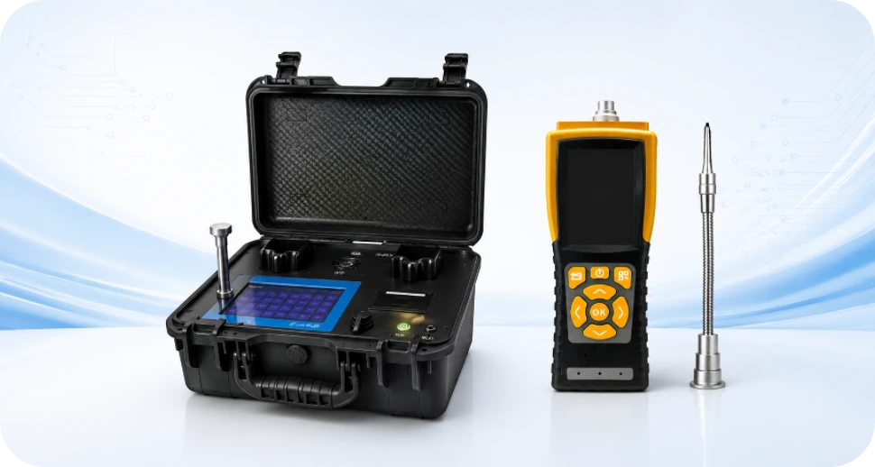
A Portable Air Quality Monitor PCB can support particulate-matter, carbon-dioxide, VOC, temperature and humidity sensing, but those measurements do not use one universal sensor principle. The approved PM, CO2 and VOC devices have different airflow, warm-up, power, contamination and calibration needs, so the manufacturing plan must follow the sensor architecture actually selected by the OEM.
Highleap Electronics manufactures customer-designed air-monitor boards with PCB fabrication, component sourcing, SMT/THT, programming, inspection, customer-defined functional testing and optional enclosure-level assembly. We support prototypes and repeat production while keeping sensor part numbers, airflow-critical mechanics and test procedures under controlled revision.
For a portable monitor, airflow is as important as routing. A technically correct PCBA can still produce poor data if the enclosure recirculates warm exhaust, the fan path is obstructed, a gas sensor is contaminated during assembly or a sensor opening is placed next to a heat source.
| Sensor target | Common product-level manufacturing concern | RFQ detail to include |
|---|---|---|
| PM1 / PM2.5 / PM10 | Defined airflow, fan/duct position, optical contamination | Exact module, inlet/outlet geometry, cleaning restrictions. |
| CO₂ | Warm-up, power peaks, pressure/temperature compensation depending on sensor | Exact sensor technology/module and factory-calibration status. |
| VOC / IAQ index | Cross-sensitivity, algorithm version, contamination | Sensor MPN, firmware/library version, burn-in or conditioning procedure if required. |
| Temperature / RH | Self-heating and enclosure bias | Sensor position, venting and thermal keep-outs. |
Start With the Pollutants and Sensor Technologies the Product Actually Uses
Portable Air Quality Monitor Product Family: PM, CO2, VOC and Multi-Sensor Devices
Portable air-quality products vary widely. A PM2.5 meter may focus on particulate mass estimates. A portable CO2 meter can be used for ventilation awareness. A VOC/IAQ monitor can track a broad gas-sensor index. Multi-sensor devices combine several of these measurements with temperature/humidity, display, logging and wireless connectivity. Personal exposure sensors emphasize small size and battery life, while tabletop portable monitors may prioritize a larger display and continuous power.
Highleap’s gas detector and sensor PCB manufacturing context is adjacent to this product family, but safety gas detectors should not be conflated with general air-quality monitors. A life-safety CO detector or combustible-gas alarm is designed and certified for a specific hazard; a consumer IAQ monitor can have a different purpose and test regime.
EPA notes that low-cost indoor air-quality monitors typically measure a limited set of pollutants and are not generally equivalent to regulatory-grade monitoring instruments. That distinction should remain explicit in product content. An OEM can still build a useful trend or informational device, but performance claims must match the chosen sensors and validation data.
Air Quality Monitor Product Types: PM, CO2, VOC and Multi-Sensor
| Monitor type | Typical measured variable | Device-level design emphasis |
|---|---|---|
| PM monitor | Particle mass/number estimates by size range depending sensor | Airflow path, fan control, contamination and optical chamber |
| CO2 monitor | CO2 concentration | Sensor warm-up, ventilation openings, calibration strategy |
| VOC/IAQ monitor | VOC-related index/equivalent signal | Algorithm, humidity/temperature compensation and exposure |
| Multi-sensor monitor | Selected combination of PM, CO2, VOC, T/RH | Airflow separation, power budget, display/logging and cross-heating |
PM, CO2 and VOC Sensor Technologies and Their PCB Implications
Optical particulate sensors use light scattering to estimate particle concentrations. Sensirion’s SPS30, for example, is a laser-scattering PM sensor that reports multiple particulate size metrics and includes its own airflow mechanism. Such modules simplify optical design but add power, connector/UART or I2C integration, orientation and air-path requirements. The factory should build around the exact sensor module selected by the OEM.
CO2 sensors can use nondispersive infrared technology or other approaches. They may have higher pulse power, warm-up requirements and sensitivity to enclosure airflow. VOC sensors are often metal-oxide devices combined with algorithms and compensation inputs. The PCB therefore has to support stable power, communication and temperature/humidity sensing where required, but the meaning of the displayed value comes from the sensor/firmware model.
Highleap’s IoT module integration in PCB manufacturing is useful when PM or gas sensors are supplied as modules. The production BOM should control exact module revision because firmware protocol, fan behavior, baseline handling or calibration may change across sensor variants.
Accuracy boundary
Do not claim that a portable monitor “detects all indoor pollutants” or is regulatory-grade unless the actual product validation supports that statement. The measured variables, sensor technology and intended use should be named precisely.
Air-Sampling Integration Notes
The sensor selection also defines what the product can legitimately claim. A particulate module may report estimated PM mass fractions, an NDIR CO2 sensor reports a gas concentration through its own optical/algorithm system, and a VOC sensor may provide an index that reacts to a mixture of gases. Those outputs should not be combined into a single “air quality accuracy” number. The PCB and firmware need to preserve each sensor’s required supply, communication and compensation inputs. During sourcing, an alternate sensor can change airflow, warm-up, protocol and calibration behavior even when it fits mechanically, so substitution should be treated as an engineering change rather than routine BOM optimization.
A multi-sensor monitor can combine PM, CO₂, VOC, temperature and humidity, but those channels should not be treated as interchangeable. A safety gas detector is a neighboring category with different alarm and compliance requirements; gas-sensor PCB manufacturing is relevant for that separate product family, not a justification to claim every IAQ monitor is a safety instrument.
Airflow Is Part of the Electrical Design
Airflow, Sensor Placement and Enclosure Design for Reliable Air Sampling
Air-quality sensing is fundamentally an air-sampling problem. PM sensors need inlet and outlet paths that allow representative flow without recirculating exhaust. CO2 and VOC sensors need ambient exchange through vents. Placing sensors directly above a warm battery, display or processor can create temperature gradients that change gas-sensor response or humidity compensation. Dust filters can protect hardware but may also alter response time if not validated.
The PCB must place sensors where the enclosure can expose them correctly. Highleap’s design-for-assembly practices are relevant because a sensor can be electrically correct yet misaligned with a vent after final assembly. Mechanical tolerances, foam ducts, gaskets and fan orientation should be inspected during first article.
Contamination control is also important. Flux residue, cleaning solvent, adhesives and conformal coating can outgas or interfere with VOC/gas sensors. Optical PM inlets must stay clean. The assembly drawing should define no-clean/cleaning requirements, sensor masking and when sensitive modules are installed relative to coating or adhesive operations.
Airflow validation can be made part of NPI with smoke visualization, pressure/flow measurements or response tests using a known stimulus, depending on the sensor. The goal is to confirm that enclosure vents feed the intended sensor instead of creating dead zones or recirculation. Fans and optical chambers can transmit vibration or acoustic noise to the housing, which may matter in bedroom or office products. Filters and membranes need documented replacement or lifetime behavior if they are service items. A PCBA factory can inspect duct/gasket placement during box build, but the OEM remains responsible for proving that the complete airflow design samples the room air representatively.
A PCB can pass electrical test while the finished monitor samples stale or internally heated air. The enclosure drawing should therefore be included in the manufacturing package so sensor openings, fans, ducts, gaskets and board placement are assembled consistently. If Highleap is asked to quote final enclosure and box-build assembly, these mechanical controls can be included in the work instructions.
MCU, Display, Logging and Wireless Functions Must Respect Sensor Timing
Air Quality Monitor PCB Architecture: MCU, Display, Logging and Wireless Connectivity
A portable monitor typically combines one or more sensor modules, MCU/SoC, display, buttons, buzzer or LEDs, memory, RTC, battery/charger and optional Bluetooth/Wi-Fi. Highleap’s Bluetooth device PCB development is relevant to phone-connected monitors, while LCD controller board integration can apply to larger graphical displays. Neither feature is mandatory for every monitor.
The MCU polls sensors, applies vendor algorithms or compensation, logs data and controls the UI. Sensor intervals can differ: a PM fan may run continuously or on a duty cycle; a gas sensor may need warm-up; temperature/humidity data can be used for compensation. Firmware version is therefore part of measurement configuration and should be controlled with the hardware BOM.
Wireless products also need antenna keep-outs and coexistence planning with noisy PM fans or switching regulators. Cloud/app connectivity is an external system. The PCBA supplier can verify Bluetooth/Wi-Fi communication and device identifiers, but app analytics, health recommendations and cloud availability are outside board manufacturing unless separately scoped.
The user interface should also communicate the measurement honestly. A color bar or “good/bad” indicator is an algorithmic interpretation layered on raw PM, CO2 or VOC values. Thresholds can vary by purpose and market, so they should be controlled in firmware rather than assumed by the assembler. Logging and wireless export should preserve units and timestamps. If a phone app is used, the PCBA production test can verify pairing and data transfer with an approved app build, while cloud analytics remain outside hardware manufacturing. This separation helps prevent a technically good sensor board from being marketed with unsupported health recommendations simply because it has a polished display.
The controller and display architecture must handle sampling intervals, sensor warm-up, logging and wireless communication without dominating the thermal environment. Products with screens may draw on LCD controller board integration experience, while app-connected monitors can benefit from Bluetooth device PCB development considerations considerations. Firmware version and communication test steps should be part of the released production data.
Battery, Fan and Sensor Warm-Up Define the Power Architecture
Battery, Charging, Sensor Warm-Up and Thermal Management
Portable air monitors can be surprisingly power-hungry because optical PM sensors, fans, NDIR CO2 sensors, displays and radios all consume energy. Battery capacity and charging architecture must be selected around the actual sensor duty cycle. Highleap’s charging circuit PCB design is relevant to rechargeable products, but the charger cannot be separated from cell chemistry, USB input and thermal constraints.
Warm-up and measurement scheduling matter. Some gas sensors need time after power-up before output is stable, while PM sensors may need airflow stabilization. Aggressive duty cycling can save power but change response time and baseline behavior. Those tradeoffs are firmware/product decisions, not something the assembler should optimize independently.
Self-heating can bias the temperature/humidity sensor and influence gas readings. Keep regulators, chargers and displays physically separated from environmental sensors where possible. In a sealed-looking enclosure, vent design must balance air exchange with dust, light and water protection. Thermal validation should use the complete device at the intended charging and measurement state.
Power scheduling should be validated with the exact sensor set because a PM fan, NDIR lamp/source and Wi-Fi radio can create overlapping current peaks. The charger and battery should tolerate those peaks without resetting the MCU or changing sensor supply enough to affect readings. Conversely, aggressive sleep modes can make the device slow to respond after wake. The OEM can define a warm-up or stabilization state shown to the user, and production should verify that state with the released firmware. Thermal mapping of the assembled enclosure is useful during development to ensure the temperature/RH sensor is not reporting heat generated by charging or the display.
Battery life should be based on the real sensor duty cycle rather than MCU sleep current alone. PM fans, NDIR CO₂ measurements, displays and radios can dominate consumption. If the board contains a rechargeable power path, battery-charging circuit PCB is relevant to the manufacturing review.
Sensor Sourcing and SMT Handling Need Device-Specific Controls
Portable Air Quality Monitor PCBA, Sensitive Sensor Handling and Component Sourcing
Assembly planning should distinguish ordinary SMT parts from sensitive air-sensor modules. Some sensors are installed after reflow or require special handling, while others are designed for standard SMT. The component vendor instructions are controlling. Highleap’s electronic component sourcing service is particularly relevant because sensor availability, exact revision and storage conditions can affect both production schedule and measurement consistency.
AOI can verify visible placement and solder joints, and AOI in PCBA manufacturing is useful for repeatable assembly screening. It cannot prove sensor accuracy or airflow. A final PCBA/box build may need sensor-specific inspection, fan direction check, vent alignment and contamination check. Highleap’s box-build assembly capability can be relevant if enclosure integration is included in the quotation.
- Variant control is important when one housing supports different sensor combinations. A PM-only SKU, CO2 SKU and multi-sensor SKU may share a PCB with different fitted modules. The production package should link BOM, firmware, calibration profile, label and test method for each variant.
- Sensitive sensor modules can also have shelf-life, moisture or contamination requirements that ordinary passives do not. Procurement should store and handle them according to vendor instructions and record the exact revision used. If a PM module is installed after SMT, the secondary assembly process should protect its inlet/outlet. If a gas sensor is SMT-mounted, reflow and cleaning limits must be followed. First-article inspection should verify vent alignment and fan orientation after the enclosure is assembled. These controls explain why turnkey air-monitor manufacturing is more than mounting a sensor: the process has to preserve the physical sampling path that gives the electronics meaning.
Sensor modules can have storage, moisture, handling, reflow or contamination limits. Highleap can combine electronic component sourcing with a focused design-for-assembly review review before production. During assembly, AOI inspection in PCBA can verify soldering and placement, but it cannot prove the air-sensing function by itself.
Calibration Strategy Must Match PM, CO2 or VOC Measurement
Calibration, Collocation and Functional Testing for Portable Air Monitors
Production testing should verify sensor communication, fan operation, display, logging, charging and wireless functions, then apply sensor-specific checks. Highleap’s PCB functional testing can be adapted to customer fixtures, but the environmental reference method is critical. A PM sensor may be checked against a reference aerosol or approved golden setup; CO2 against known gas concentrations; temperature/humidity against a chamber or reference probe.
Calibration strategy depends on the sensor. Some modules are factory calibrated and should not be recalibrated by the PCBA factory; the production line may only verify plausibility. Others use product-level offsets or collocation correction. EPA materials discuss collocation as an important way to evaluate low-cost air-sensor performance against reference monitors. If the OEM uses such a correction model, its coefficients and firmware must be revision-controlled.
- Do not turn a production pass/fail screen into an unsupported regulatory claim. A device can be internally consistent and useful for trends without meeting an ambient-air regulatory method. The test report should state what was measured, what reference was used and the acceptance limits supplied by the customer.
- Collocation is particularly valuable during product development because it reveals combined sensor, enclosure and algorithm behavior under real air conditions. It is not necessarily an efficient 100% production test. Once the design is characterized, routine production can use shorter functional/reference checks to catch wrong modules, blocked fans, bad communication or gross sensor drift. The OEM should define which coefficients are factory-set by the sensor vendor and which, if any, are adjusted in the finished product. Test records should include firmware and sensor revision so performance changes can be traced when a supplier updates a module or algorithm.
Some sensor modules arrive factory calibrated; others require product-level offsets, conditioning or reference checks. The manufacturing plan should state which measurements are calibration, which are plausibility checks and which require controlled reference equipment. A customer-defined functional testing for assembled PCBs flow can verify sensor communication, display, buttons, storage, charging, fan operation and wireless functions.
Prototype the Air Path Before Scaling the PCBA
Use air-monitor prototype PCB builds to test the assembled PCB inside the real enclosure. Early builds should reveal whether processor/display heat biases temperature or humidity, whether the PM inlet is blocked, whether the fan causes vibration or noise issues, and whether warm-up current causes resets.
A pilot run should then prove sensor sourcing, assembly handling, firmware loading, calibration/reference steps and fixture throughput. Only after those controls are stable should the product move into repeated batch production.
Cost Is Often in the Sensors and Test Time, Not the Bare PCB
The most expensive line items are often PM/CO₂ sensor modules, display and wireless hardware, battery/fan assemblies, enclosure work and calibration/reference time. PCB layer count may be modest compared with the sensor BOM. A useful quote therefore separates PCB fabrication, component cost, PCBA, programming, calibration/functional test and optional final assembly.
Send Gerber/ODB++, fabrication notes, BOM with exact sensor modules, assembly files, enclosure/airflow drawings, power requirements, firmware, calibration/test procedure, target quantities, labels and packaging requirements.
A Good PCBA Cannot Correct a Bad Air Path
For quotation, send the PCB fabrication package, exact sensor BOM, pick-and-place, assembly drawings, enclosure and airflow files, fan or pump details where applicable, battery/charging requirements, firmware, calibration or reference procedure, functional-test limits, labels, packaging and target quantities. If different SKUs use different sensor combinations, identify them separately.
Highleap can control the manufacturing variables it owns—PCB fabrication, sourcing, component handling, assembly, inspection, programming and the customer-defined test flow. Prototype builds should be used to check the completed air path and thermal layout before large material commitments, because moving a vent, fan, battery or display can change sensor exposure without changing the schematic.
A good PCBA cannot correct a bad air path. The best production result comes when sensor technology, mechanical sampling, thermal behavior and the manufacturing process are released as one system. That is the package Highleap can build consistently from sample quantities into repeat production.

Recommended Posts

TMM4 Filter PCB Manufacturing
TMM4 filter PCB manufacturing is controlled by the...

TMM3 PCB Manufacturing for RF Modules
TMM3 PCB manufacturing is most useful where the RF module...

TMM6 PCB Fabrication
TMM6 fabrication is the process-control page for a mid-Dk...

TMM10 PCB Manufacturing for Compact RF Designs
Table of contentsHow TMM10 Shrinks RF StructuresTMM10 vs...
How to get a quote for PCBs
Let’s run DFM/DFA analysis for you and get back to you with a report. You can upload your files securely through our website. We require the following information in order to give you a quote:
-
- Gerber, ODB++, or .pcb, spec.
- BOM list if you require assembly
- Quantity
- Turn time
For PCBA services, please provide your BOM (Bill of Materials) and any specific assembly instructions. We also offer DFM/DFA analysis to optimize your designs for manufacturability and assembly, ensuring a smooth production process.