
Barcode Label Printer PCB Manufacturing for Thermal, Transfer and RFID Label Systems
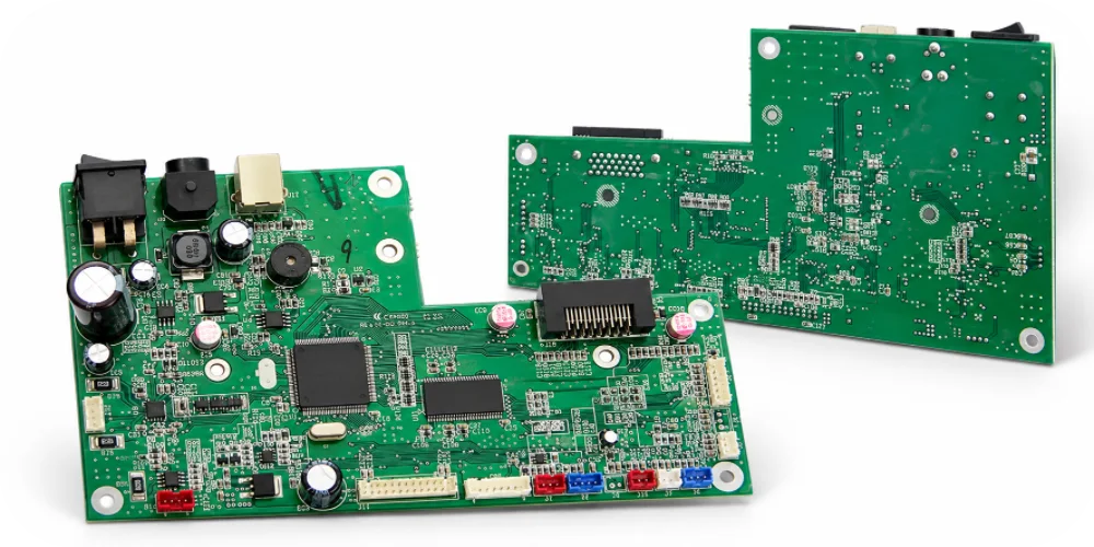

Two barcode label printers can use the same thermal printing method and still need different PCB assemblies. A compact desktop printer may combine its printhead driver, media-feed motor control, sensors and USB interface on one board. An industrial thermal-transfer model can add ribbon-drive circuits, a separate operator-panel PCBA, cutter or peeler control and, on certain models, an RFID encoding module. The manufacturing question is not simply whether a factory can populate a printer mainboard; it is whether the released electronics match the actual print mechanism and option set.
Highleap Electronics manufactures customer-designed barcode label printer PCBs and PCBAs as part of its wider electronic manufacturing services. We support PCB fabrication, approved component sourcing, SMT and through-hole assembly, inspection and agreed functional tests. We do not manufacture a standard Highleap-branded label printer. For an OEM build, the printhead specification, wiring, motors, media sensors, firmware and assembly drawings establish what the factory is actually making.
Barcode Label Printer PCB Assemblies by Printer Configuration
Barcode label printer PCB manufacturing can involve one integrated controller board or several interconnected assemblies. The number of PCBs is determined by the released mechanism, available space and options, not the product category alone.
- Desktop direct-thermal label printer: Often an integrated controller PCBA with printhead connection, feed-motor driver, gap/black-mark sensor inputs, USB or another specified host interface, and status controls. No ribbon motor is required for direct-thermal-only operation.
- Desktop or industrial thermal-transfer printer: Adds ribbon detection and motion-related circuitry to the printhead and media-feed system. The ribbon mechanism may have separate motor or sensor boards depending on its design.
- Industrial barcode printer: May distribute the main controller, power input, display/keypad, communication interface and motor-related circuits across different boards. Heavy connectors and optional mechanisms can change the SMT/THT assembly sequence.
- RFID or print-and-apply configuration: May incorporate an approved UHF encoding module, antenna interface, applicator I/O or additional sensors. These are model-specific options, not standard components of every barcode printer.
Before ordering, identify the complete printer PCBA set: each board’s part number, revision and quantity per printer; the mating direction and pinout of board-to-board interconnects; and what is supplied as an assembled module instead of a bare electronic component. A BOM for the controller alone will not price the ribbon-control or cutter PCBA if those are separate assemblies.
There is also an important boundary between a label-printer controller and its printing mechanism. Highleap can build the specified electronics. Printhead selection, pressure adjustment, media-path design and complete printer performance are defined by the OEM’s released product and acceptance procedures.
Thermal Printhead Driver PCB: Resolution, Energy and Power
The thermal head is not a generic load. A printer family might offer 203, 300 or 600 dpi variants, but the head width, dot count, resistance, timing, thermistor characteristics and connector arrangement must still be matched to the specific model. Reusing a controller layout does not make different heads automatically interchangeable.
What a printhead variant changes in the production release
The relevant thermal printhead driver PCB may contain driver ICs or switching devices, power distribution, protection and control signals. Its approved component population needs to agree with the head’s electrical specification and the firmware’s energy or strobe settings. In a thermal-transfer model, heat is applied through a ribbon; in direct-thermal printing, it acts on thermally sensitive label stock. Both depend on correct head timing and a stable media feed.
During component procurement, a seemingly similar MOSFET, connector or power device should not be substituted without approval. Switching characteristics, contact resistance and thermal behavior can affect the delivered pulse. Related thermal printing controller electronics considerations apply, but the released barcode-printer head and firmware must remain the manufacturing reference.
A useful first-article PCBA check distinguishes electrical readiness from printed-label performance. Voltage and driver outputs can be tested with an approved load or fixture, while a real printhead and specified label stock are needed for the agreed print test. Dense black areas or long solid bars can stress the printhead power-distribution path more than a short text label. The actual test pattern, print speed and acceptable supply behavior should come from the OEM rather than a universal factory setting.
Media Sensor and Motor Control PCBA for Accurate Label Feeding
Many apparently electrical label-printer failures originate at the boundary between the PCB and the media mechanism. If the gap sensor misses an edge, the next label begins in the wrong place. If the feed motor loses steps or the ribbon wrinkles, a perfectly functioning printhead may produce a distorted or incomplete barcode.
Gap sensors and black-mark sensors need real label stock
A transmissive gap sensor detects differences through the label and liner; a reflective black-mark sensor responds to markings on the media backing. Neither should be qualified with an arbitrary sample if the printer is intended to handle multiple approved label stocks. The useful reference is the OEM’s actual range of liner opacity, gap or mark dimensions, calibration procedure and feed speed.
For a label printer sensor PCB assembly, confirm emitter/receiver orientation, connector pinout, sensor-board mounting position and the defined calibration response. When a problem appears only on one type of label, the engineering review should compare the sensor’s readings and media settings before treating it as an SMT defect.
Feed motors, ribbon drives and timing belong in one acceptance sequence
The feed motor, printhead strobe and top-of-form sensor are coordinated by the printer’s control system. Thermal-transfer designs add ribbon take-up behavior; a change in ribbon drag or winding conditions may affect print registration even when the feed motor driver passes an isolated electrical check. Drive-motor control boards are therefore relevant to some printer designs, but the complete motion profile is controlled by the released firmware and mechanism.
For the first approved build, it is useful to record one repeatable print sequence: load the specified media, perform the intended calibration, print a known label at the agreed speed, advance to the next label and check the printed start position. This makes a sensor or harness assembly problem easier to separate from unsuitable media settings, rather than adding an unexplained “print OK” result to the inspection report.
Cutter, Peeler, Rewinder and RFID Printer Board Options
One industrial printer family may share a controller platform while offering several different mechanical options. That can be efficient for the OEM, but only when the PCBA variants remain controlled. A cutter needs a driver and a position or home indication; a peeler may use label-present sensing; a rewinder adds another controlled load. None of those interfaces should be populated, powered or tested merely because an optional footprint exists on the PCB.
RFID label printer PCB assembly adds a different set of constraints. A UHF reader/encoder and antenna path must correspond to the approved hardware and label inlay arrangement. Encoding results can depend on where the inlay sits relative to the antenna and on the surrounding mechanical structure. Highleap should not be described as qualifying every tag type or regional RF configuration as part of ordinary board assembly.
Use a model-specific assembly and programming record
A helpful production matrix identifies the printhead version, populated options, harnesses, firmware package and test routine for each sellable printer model. The same bare PCB may require a different BOM or programming image for a cutter-equipped version, a higher-resolution head or a network-enabled variant. If the controller is programmed during PCBA production, the released printer-language implementation, communication configuration and option settings must be matched to the hardware revision.
Component availability needs the same discipline. A last-minute change to a head connector, motor driver, RFID module or configuration memory may affect both assembly and system behavior. Highleap can coordinate purchasing of approved printer components; substitute parts and variant changes still require OEM authorization.
Quoting a Label Printer Controller? Include the Print Mechanism and Options.
Along with Gerber files and the BOM, share the printhead model, feed-motor and sensor interfaces, media type, cutter/peeler/RFID options and required print-test procedure. Highleap can review the defined PCB fabrication, sourcing, assembly and test scope for each printer-board variant.
| Get My Quote | Discuss My Build |
Manufacturing and fixture scope are agreed against the released printer configuration.
Barcode Printer PCB Manufacturing, Functional Testing and RFQ
A barcode label printer PCBA may combine fine-pitch control electronics, high-current printhead or motor drivers, large through-hole connectors and optional communication modules. Assembly planning should account for the actual part mix: PCB panel support, stencil and reflow requirements, connector soldering, optical sensor handling and access for programming or test probes. These are manufacturing decisions tied to the released design, not a claim that every label printer needs an exotic PCB process.
Define the test by the printer behavior that matters
Visual inspection, automated optical inspection of soldered assemblies and electrical checks can screen workmanship defects. They do not prove that a controller prints correctly at the intended speed with the approved labels. When the customer supplies the fixture and acceptance method, Highleap can discuss customer-defined printer functional tests that cover the populated electronics and, where included, a representative print cycle.
Four observable outcomes help specify a useful pilot test:
- Stable head and motor power: Confirm the agreed electrical limits while printing a specified dense pattern, rather than only checking the idle supply.
- Repeatable label registration: Use approved gap or black-mark media and record whether successive labels start within the OEM’s position tolerance.
- Correct option behavior: Exercise only the fitted cutter, peeler, rewinder, communication or RFID assemblies with their released test sequence.
- Correct programming: Confirm the hardware variant, printhead settings, firmware and, where applicable, device/network identity match the order.
When the printed output is unsatisfactory, the production record should help narrow the investigation rather than label every symptom a defective PCB. Light or missing bars may warrant checking head energy, ribbon and media; vertical label drift points toward sensor calibration, feed and mechanical alignment; a cutter jam calls for the cutter mechanism, driver and home signal to be checked together. These are diagnostic directions, not automatic fault diagnoses.
Print darkness, barcode symbol verification grades, supported media range, cutter endurance and RFID encode reliability require customer-defined system acceptance. For example, a printed barcode that scans in a quick station test is not automatically a verified barcode grade under the applicable standard. Those broader qualifications should not be represented as included unless explicitly contracted.
What to send for a useful barcode label printer PCB quote
- PCB and PCBA data: Gerber/ODB++, fabrication drawings, stack-up, approved BOM, placement files and assembly drawings for every board.
- Print mechanism: Printhead manufacturer/part number, resolution, width, connection drawing, input supply and feed-motor details.
- Media and options: Intended direct-thermal or thermal-transfer configuration, gap/black-mark sensor type, ribbon mechanism, cutter/peeler/rewinder or RFID parts as fitted.
- Firmware and acceptance: Programming images, configuration matrix, reference label/ribbon, test pattern, speed and pass/fail criteria for the operations to be included.
- Purchasing scope: Quantity per PCB variant, prototype and repeat-order volumes, consigned parts, modules supplied by the OEM, and whether mechanical integration or fixtures require separate quotation.
For an OEM that wants the bare boards, approved electronic parts and populated assemblies sourced together, Highleap’s integrated board fabrication and assembly service can be quoted against that released board set. A clear model-and-option list avoids comparing a controller-only assembly price with a quote that also includes sensors, power boards and print-cycle testing. That is the information needed to move from a working printer prototype to a reproducible PCBA order.

Recommended Posts
TMM4 Filter PCB Manufacturing
TMM4 filter PCB manufacturing is controlled by the...
TMM3 PCB Manufacturing for RF Modules
TMM3 PCB manufacturing is most useful where the RF module...
TMM6 PCB Fabrication
TMM6 fabrication is the process-control page for a mid-Dk...
TMM10 PCB Manufacturing for Compact RF Designs
Table of contentsHow TMM10 Shrinks RF StructuresTMM10 vs...
How to get a quote for PCBs
Let’s run DFM/DFA analysis for you and get back to you with a report. You can upload your files securely through our website. We require the following information in order to give you a quote:
-
- Gerber, ODB++, or .pcb, spec.
- BOM list if you require assembly
- Quantity
- Turn time
For PCBA services, please provide your BOM (Bill of Materials) and any specific assembly instructions. We also offer DFM/DFA analysis to optimize your designs for manufacturability and assembly, ensuring a smooth production process.