
Collaborative Robot PCB for Cobot Safety and Joint Control
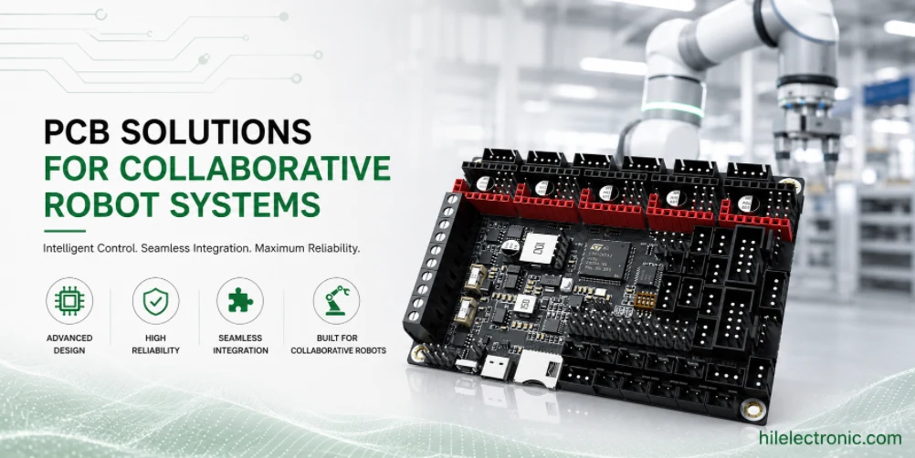
Collaborative robot PCBs support robots that operate near people, so their electronics must combine motion control, force sensing, safety I/O, brake control, communication, and repeatable manufacturing. A cobot PCB article should not only explain what a cobot is; it should help engineers and buyers understand how PCB fabrication, PCBA assembly, testing, and documentation influence safety-related product behavior.
Highleap Electronics manufactures and assembles PCBs for robotics customers, including boards that need careful DFM, sensing accuracy, traceability, and production test coverage. Product certification remains the responsibility of the robot manufacturer, but PCB manufacturing discipline affects whether the customer has reliable hardware evidence for validation.
What Collaborative Robot PCBs Must Do in Real Cobot Systems
Human-Proximity Operation Changes the Electronics Requirement
Collaborative robots use electronics to supervise contact forces, joint torque, speed limits, safe stops, brake status, end-effector state, and operator interaction. The PCB must preserve signal quality and predictable behavior under normal operation and fault conditions. This makes cobot electronics closer to a controlled manufacturing product than a simple controller board.
The design must also be serviceable. Cobots are often installed in factories, laboratories, and flexible production cells. Replacement boards, connector identification, revision control, and test records help maintenance teams understand whether a problem is mechanical, electrical, or software-related.
How PCBA Quality Affects Safety-Related Behavior
Force sensing, encoder feedback, motor current measurement, and safety input circuits are sensitive to assembly variation. Bad solder joints, noisy analog front ends, weak isolation, or inconsistent connector retention can create faults that are difficult to diagnose. A cobot PCB needs manufacturing controls that preserve the design margins established by engineering.
Cobot electronics often connect to robot safety I/O PCB architecture, robot sensor PCB assembly, and servo and BLDC controller PCB design. These board categories should be reviewed together because motion, sensing, and safety decisions interact at the system level.
Safety I/O, Force Sensing, Brake Control, and Motion Electronics
Safety I/O and Stop Functions
Safety I/O boards handle emergency stop inputs, enabling devices, protective stops, light curtains, safety scanners, and monitored outputs. The PCB layout must support isolation, redundancy, clear separation, diagnostic test points, and predictable fail-safe behavior. Manufacturing should preserve creepage, clearance, connector orientation, and solder quality on these circuits.
PCB content should avoid claiming that a board alone makes a cobot certified. Standards evaluation happens at product level. The PCB role is to provide reliable hardware paths, documentation, and production consistency that the robot manufacturer can include in validation.
Force, Torque, Encoder, and Joint Control Signals
Force and torque sensing often uses strain gauges, torque sensors, current sensing, or model-based monitoring. These circuits need low noise, stable references, proper filtering, and repeatable calibration. Encoder and position feedback require clean differential routing, connector shielding, and validated cable interfaces.
Joint controller PCBs may also include motor drive stages. In those cases, robot motor driver PCB engineering, thermal dissipation, and EMC containment must be reviewed together. Mixing precision sensing and high-current switching on compact boards requires careful partitioning.

DFM Risks in Cobot PCB Fabrication and Assembly
Mixed-Signal Layout and Isolation Risk
Cobot boards often combine analog sensing, safety inputs, digital processing, communication interfaces, and motor-related power circuits. DFM review should check creepage, clearance, test point access, ground partitioning, controlled impedance where needed, and separation between noisy and sensitive circuits.
Assembly risks include fine-pitch ICs, connectors with high insertion force, shield cans, large inductors, and safety-related optocouplers or digital isolators. The BOM should clearly identify parts that should not be substituted without engineering approval.
Connector, Harness, and Serviceability Details
Cobot electronics are installed inside arms, controllers, end-effectors, and teach interfaces. Connector orientation, locking style, harness bend direction, and board mounting all affect assembly time and field service. These mechanical details must be visible in the assembly drawing and not left to production interpretation.
rigid-flex PCB for robotics may reduce connector count in compact joints, while standard harnesses may be easier to service in control cabinets. The best solution depends on cycle life, joint motion, service plan, and production volume.
PCBA Testing, Traceability, Firmware, and Safety Documentation
Functional Test Coverage for Cobot Boards
A cobot PCBA test plan should verify power rails, safety input state, output switching, encoder communication, sensor readings, brake signals, current measurement, communication ports, and firmware identity. Test results should be tied to board revision and serial number when validation records matter.
Functional testing should include fault-like conditions where practical, such as open input, shorted output, overcurrent indication, or sensor out-of-range detection. The goal is not to certify the robot at PCBA level, but to prevent manufacturing defects from reaching system validation.
Traceability for Controlled Product Changes
Cobot programs need stable revision history. PCB fabrication revision, BOM revision, firmware image, programming date, test fixture version, and operator records can all matter when investigating a field issue. Without traceability, a small component substitution may become impossible to correlate with behavior changes.
robot PCB assembly documentation documentation should define test points, programming method, label format, and inspection criteria before the pilot build. This reduces uncertainty when the product transitions from engineering builds to repeatable orders.
EMC, Thermal, Mechanical, and Long-Life Reliability Decisions
EMC and Noise Control in Human-Adjacent Robots
Cobots combine motor switching, Ethernet or fieldbus, sensors, safety devices, and sometimes wireless modules. EMC failures may appear as false stops, communication loss, sensor drift, or unexpected fault states. Layout, filtering, shielding, grounding, cable termination, and enclosure connection should be reviewed before certification testing.
The robot PCB EMI and EMC design topic is especially important because cobots operate near people and other industrial equipment. Immunity matters as much as emissions. A board that works in isolation may behave differently inside a full robot cell.
Thermal and Mechanical Life in Compact Joint Electronics
Joint and wrist electronics can be compact, warm, and exposed to repeated motion. Thermal vias, copper planes, component placement, board thickness, and mechanical support affect long-term reliability. Large components need support when the board is mounted in moving structures.
Long-life cobot boards should avoid relying on undocumented assembly choices. Adhesive use, fastener torque, heatsink attachment, and cable retention should be specified clearly so the same design is built consistently over time.
Prototype, Validation, and Production Transfer for Cobot PCBs
Prototype Builds Should Preserve Validation Evidence
Prototype cobot PCBs often include debug access, measurement points, and extra indicators. These features are valuable during development but should be controlled as the product moves toward production. Removing them without updating the test method can reduce manufacturing visibility.
Validation builds should use production-intent materials, fabrication notes, assembly process, and test procedures as early as possible. Otherwise, the team may validate one version and manufacture another.
Pilot Runs Should Measure More Than Electrical Pass Rate
A pilot run should collect solder yield, connector defects, programming failures, functional test results, calibration repeatability, and rework causes. This data helps decide whether the board is ready for repeat production or still needs DFM changes.
Cobot electronics may also connect with industrial robot PCB manufacturing pages when the product shares industrial robot communication, cabinet architecture, or safety expectations. Interlinking these topics helps both users and search engines understand the robotics manufacturing context.
RFQ Package Details That Improve Quotation Accuracy
For a collaborative robot PCB RFQ, include the safety I/O architecture notes, sensor interface requirements, torque or current measurement expectations, brake-control signals, firmware loading plan, test limits, board revision rules, and any product-level validation constraints.
- safety-related inputs and outputs clearly identified
- sensor calibration or measurement accuracy requirements
- encoder, brake, motor, and end-effector interface list
- firmware image, bootloader, and programming method
- serial-number traceability and revision-control needs
- functional test cases for fault-like conditions where practical
Production Release Checks Before Scaling
Before production release, the PCB should be reviewed for traceability and change control. A cobot hardware change may affect validation, so substitutions and process changes should not be treated as ordinary purchasing decisions.
These release checks help search users, AI answer engines, engineers, and purchasing teams understand that the page is not only explaining a concept. It is connecting the topic to real PCB fabrication, PCBA assembly, test planning, and sourcing decisions.
Common Design and Manufacturing Mistakes to Avoid
Common cobot PCB mistakes include mixing noisy drive circuits with precision sensing, leaving safety connector orientation ambiguous, treating torque sensing as a generic analog input, and allowing component substitutions on measurement or isolation circuits without engineering approval.
- safety I/O not clearly separated in layout and documentation
- force or torque sensing without calibration and noise budget
- brake control outputs tested only as static digital signals
- firmware loading process not tied to board serial number
- substituted isolators, sensors, or references without review
- connector labels and harness directions missing from assembly drawings
Highleap Electronics Collaborative Robot PCB Manufacturing and Assembly Support
What the Manufacturing Package Should Include
Highleap Electronics reviews PCB fabrication data, assembly files, BOM details, and test requirements before production. For collaborative robot pcb, the RFQ package should include Gerber or ODB++ data, stackup target, BOM, assembly drawings, safety I/O notes, sensor calibration requirements, firmware loading instructions, test plan, volume estimate, and revision-control expectations. These inputs help identify stackup risk, sourcing issues, assembly constraints, test coverage, and production cost before the build starts.
A complete package also reduces email back-and-forth. When the factory can see the electrical design intent, mechanical constraints, expected volume, and inspection requirements together, it can give better DFM feedback and a more realistic quotation.
How Highleap Helps Convert Design Intent Into Buildable PCBA
Cobot PCB builds require care because a manufacturing defect may show up as a motion, sensing, or safety-related fault during system validation. Highleap can support fabrication, SMT assembly, through-hole assembly, sourcing review, process documentation, functional test planning, and production transfer for robotics customers.
For prototype, pilot, or production builds, the manufacturing package can be reviewed for DFM, PCBA, sourcing, test, and traceability risks. Request a PCB manufacturing and assembly review.
What Buyers Should Check Before Choosing a PCB/PCBA Supplier
Purchasing teams should look for a PCB/PCBA supplier that can maintain revision discipline. Cobot electronics often support product validation, so the factory must control BOM changes, firmware process, traceability, and functional test records carefully.
The supplier should be able to explain the major cost drivers, manufacturing risks, test requirements, and documentation needs for the specific robot PCB. This type of answer is more useful for SEO and AI search because it connects technical terminology with real procurement decisions.
Collaborative Robot PCB FAQs
What is a collaborative robot PCB?
It is a PCB used in a cobot system for joint control, force sensing, safety I/O, communication, brake control, end-effector connection, or central supervision.
Which PCB signals matter most in cobot safety?
Safety inputs, brake status, encoder feedback, torque or current sensing, emergency stop paths, and monitored outputs are usually the most safety-sensitive PCB signal groups.
Why do cobot PCBs need low-noise sensing?
Low-noise sensing helps the robot detect force, torque, current, and position accurately. Poor signal quality can affect contact detection and motion smoothness.
Can a PCB make a cobot safety certified?
No. Safety certification is evaluated at robot system level. The PCB contributes reliable hardware paths, documentation, and manufacturing consistency for product validation.
What causes cobot PCB assembly failures?
Common causes include connector stress, poor isolation spacing, noisy mixed-signal layout, weak solder joints, firmware mismatch, insufficient test coverage, and uncontrolled component substitutions.
How should cobot PCBs be prepared for production?
Use production-intent stackup, approved BOM alternates, fixture-ready test points, firmware control, serial labels, assembly drawings, and documented functional test limits before scaling.

Recommended Posts

TMM4 Filter PCB Manufacturing
TMM4 filter PCB manufacturing is controlled by the...

TMM3 PCB Manufacturing for RF Modules
TMM3 PCB manufacturing is most useful where the RF module...

TMM6 PCB Fabrication
TMM6 fabrication is the process-control page for a mid-Dk...

TMM10 PCB Manufacturing for Compact RF Designs
Table of contentsHow TMM10 Shrinks RF StructuresTMM10 vs...
How to get a quote for PCBs
Let’s run DFM/DFA analysis for you and get back to you with a report. You can upload your files securely through our website. We require the following information in order to give you a quote:
-
- Gerber, ODB++, or .pcb, spec.
- BOM list if you require assembly
- Quantity
- Turn time
For PCBA services, please provide your BOM (Bill of Materials) and any specific assembly instructions. We also offer DFM/DFA analysis to optimize your designs for manufacturability and assembly, ensuring a smooth production process.