
Document Camera PCB Manufacturing & Assembly for USB, HDMI and Classroom Visualizers
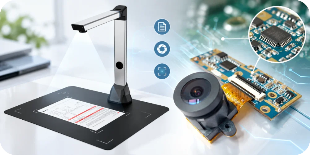

Highleap Electronics provides PCB fabrication and PCB assembly for document camera equipment, including classroom visualizers, overhead document cameras, portable presentation cameras and document-imaging systems. We support customer-supplied designs from prototype builds through repeat production, with manufacturing review covering PCB layout and stack-up, camera-sensor or module connections, FPC interfaces, illumination circuits, video interfaces, component sourcing and functional-test requirements.
If you are sourcing a PCB for a document camera, the manufacturing plan depends on the released design, not just the product name. Send us your fabrication data, BOM, assembly files, target quantity and test requirements so we can review your actual product configuration.
PCB Types Used in Document Camera Equipment
A document camera may use one main board or several interconnected boards. The configuration depends on the imaging architecture, output interfaces, lighting, controls and mechanical design. These differences affect PCB fabrication, component placement, cable routing and the tests required before shipment.
USB Document Cameras
A USB document camera may combine an image sensor or camera module, image-processing or bridge circuitry, a USB interface, buttons and LED lighting. The exact USB mode and video behavior must be confirmed from the approved schematic, controller and firmware. A USB connector alone does not establish the supported data rate or video format.
HDMI Document Cameras and Classroom Visualizers
Models with HDMI output may include local video processing, output circuitry, protection components and additional power rails. The PCB fabrication package should identify any controlled-impedance requirements, while assembly and functional testing should use the intended display path and the customer’s acceptance criteria.
Portable and Folding Document Cameras
Compact and folding products can use a small camera-head PCB connected to a main board by a flexible printed circuit or cable assembly. Board outline, connector orientation, hinge movement, cable bend radius and strain relief should be reviewed together with the mechanical drawings. Related camera FPC requirements can be reviewed alongside the PCB build.
Motorized or Autofocus Visualizers
Products with motorized focus, zoom or positioning may add motor drivers, actuator connectors, feedback signals and higher transient-current loads. The assembly and test plan should identify the actual actuator and required movement sequence rather than assume all visualizers use the same mechanism.
Document-Imaging Systems with Displays or Network Functions
Some designs include a local preview display, touch controls, Ethernet or wireless connectivity, audio, memory or additional peripheral boards. These functions should be listed in the product configuration so that the BOM, assembly instructions and test procedure match the correct hardware variant.
PCB Design and Manufacturing Review
Before quoting a document camera circuit board, Highleap reviews the supplied manufacturing data and requirements that can affect cost, yield or assembly. The goal is to manufacture the released design accurately and identify missing or conflicting information before production, rather than make unapproved changes to the customer’s circuit.
- Fabrication data: Gerber or ODB++ files, drill data, board outline, layer count, finished thickness, copper weight, surface finish and fabrication notes.
- Stack-up and routing: controlled-impedance requirements, differential-pair notes and specified material or tolerance requirements.
- Mechanical interfaces: mounting holes, enclosure clearances, camera-head position, connector access and board-to-board alignment.
- Assembly constraints: fine-pitch ICs, small passive components, FPC connectors, sensor modules, shielding and keep-out areas.
- Revision control: matching revisions for PCB files, BOM, assembly drawing, firmware and functional-test procedure.
A documented DFM review helps identify fabrication or assembly questions before a build starts. For designs requiring board production and component mounting, Highleap can coordinate PCB assembly using the approved fabrication data and BOM.
Camera Sensor, Module and FPC Connections
The camera interface is one of the key areas to review when manufacturing a PCB for a document camera. The image sensor may be mounted directly on the board, supplied as a preassembled camera module or connected to the main PCB through an FPC. Each arrangement has different assembly, handling and verification requirements.
- Approved component identity: identify the exact sensor or camera-module part number and revision. Similar package dimensions or nominal resolution do not automatically make modules interchangeable.
- Connector orientation: specify FPC contact direction, pin assignment, insertion depth and connector location. Confirm that the mechanical drawing matches the assembly data.
- Power and signal requirements: preserve the released power rails, clocking, filtering, decoupling and routing constraints. Changes should be approved by the design owner.
- Clean handling: define handling and cleanliness requirements for exposed sensors, optical windows and lens interfaces. Confirm whether optical assembly takes place during PCBA production or at a later system-assembly stage.
- Mechanical alignment: verify board datums, mounting features and camera-module position against the supplied enclosure or fixture data.
Where the design uses a separate camera board, Highleap can review the relevant camera PCB manufacturing requirements together with the interconnect and assembly documentation. Optical tuning, lens selection and image-processing performance remain defined by the product owner unless they are explicitly included in the contracted scope.
Lighting, Controls and Auxiliary Circuits
Document cameras often include more than imaging electronics. LED illumination, buttons, rotary controls, microphones, displays and motorized mechanisms may be integrated on the main board or implemented on separate PCBs. These circuits should be included in the BOM and functional-test plan whenever they are part of the released product.
- LED illumination: confirm LED part numbers, driver circuitry, polarity, connector pinout and thermal requirements. Test current or illumination behavior against the customer’s defined limits.
- Buttons and encoders: check component orientation, actuator height, soldering and expected input response.
- Display connections: review FPC seating, panel power, backlight connections and touch interfaces where present. Related display PCB manufacturing requirements may need a separate review.
- Motor and actuator circuits: confirm driver components, connector ratings, protection circuitry and the test fixture needed to operate the actual mechanism.
- Audio or networking: identify microphone, Ethernet or wireless components in the approved BOM and define required test coverage for each product variant.
Not every document camera uses all these features. The manufacturing scope should follow the supplied design and approved configuration rather than assumptions based on the product category.
USB, HDMI and Network Interface Requirements
Interface requirements should come from the released schematic, layout, component data and firmware configuration. USB, HDMI, Ethernet and wireless connections have different electrical and test requirements, so the interface list should be clear before the PCB is released for production.
- USB: review connector footprint, ESD protection, differential-routing requirements and mechanical support. Where USB-C is used, confirm the approved receptacle, CC circuitry and power configuration. See the related USB-C connector assembly considerations.
- HDMI: follow specified routing, protection and connector requirements. Validate the output using the intended display or an approved test setup.
- Ethernet or wireless: review relevant magnetics, antenna keep-outs, grounding and configuration requirements when these functions are present.
- Internal cables: include camera-head cables, USB harnesses and internal FPCs in pilot builds if they affect mechanical fit or signal behavior. Related PCB cable assembly requirements can be reviewed with the board assembly.
Where the design specifies controlled impedance, the fabrication drawing should state the required impedance and reference stack-up information. Highleap can review these requirements during manufacturing preparation; interface performance must be verified using the agreed test method and system configuration.
Highleap Electronics | PCB Fabrication & PCBA
Need a Quote for Your Document Camera PCB?
Send your PCB fabrication files, BOM, assembly data, target quantities and test requirements. We will review the supplied package and clarify any missing information needed to prepare a manufacturing quotation.
PCB fabrication and assembly · DFM review · Prototype and repeat production
PCB Assembly, Inspection and Functional Testing
For a document camera PCBA, assembly quality is only one part of release readiness. The production plan should also identify programming needs, interface checks and the functions that must be verified before shipment. Test coverage should be agreed with the customer rather than inferred from the product name.
Assembly and Inspection
Assembly preparation covers the approved BOM, component orientation, polarity, fine-pitch packages, FPC connectors and any sensor or module handling requirements. Automated optical inspection (AOI) can be used for applicable visible solder-joint and placement criteria. Hidden joints or other specific risks may require additional inspection methods according to the package and acceptance plan.
Programming and Functional Checks
If programming is part of the order, the customer should provide the approved firmware or configuration package and identify the relevant hardware revision. Functional testing may include the following items when they are in scope:
- Power-up and current consumption against defined limits.
- Camera detection, image capture or video streaming using the specified host or test fixture.
- USB, HDMI or network interface checks for the interfaces fitted to that variant.
- LED illumination, buttons, display, audio or motorized functions where fitted.
- Connector retention, cable routing and mechanical fit in a representative fixture or enclosure.
Image quality, focus, color performance and optical calibration may depend on the sensor, lens, lighting, firmware and mechanical stack. If these are acceptance criteria, the RFQ should state the target, test method, fixture and pass/fail limits. This avoids treating a basic electrical test as proof of complete optical performance.
Prototype Builds and Repeat Production
Prototype builds are most useful when they represent the intended production configuration. If the camera head, FPC, lighting board, enclosure, display or motor assembly affects fit or operation, include the relevant parts early enough to validate the full assembly—not just a bare PCB.
- Engineering review: check fabrication data, stack-up notes, board outline, BOM and assembly drawings.
- Prototype fabrication: manufacture the PCB to the approved design and document open technical questions before assembly.
- Assembly preparation: confirm component availability, approved alternates, package orientation and special handling instructions.
- First-build verification: run the agreed inspection, programming and functional tests; record issues against the relevant board and BOM revisions.
- Production release: freeze the approved data package, component substitutions, firmware version, test fixture and acceptance criteria before repeat orders.
Highleap can coordinate rapid PCB prototyping, component sourcing and assembly for prototype and production builds. Lead time and pricing depend on board specifications, BOM availability, build quantity, test scope and special mechanical or optical requirements.
For projects with long-lead or allocation-sensitive components, electronic component sourcing can be reviewed alongside the BOM. Any substitute for a sensor, processor, memory device or other controlled component should be approved by the customer before use.
What to Include in a Document Camera PCB Quote Request
To quote a PCB for document camera equipment accurately, provide the technical files and identify the intended manufacturing scope. A board photograph or product label alone is not enough to determine fabrication, assembly or test requirements.
- PCB fabrication: Gerber or ODB++ data, drill files, fabrication drawing, stack-up, board thickness, copper weight, surface finish and quantity.
- PCB assembly: BOM with manufacturer part numbers, centroid or pick-and-place file, assembly drawing and approved alternate list.
- Camera and interconnect details: sensor or module part number, FPC specifications, connector orientation and relevant mechanical drawings.
- Production configuration: board revision, product variants, firmware or programming requirements and no-substitute components.
- Test requirements: functional procedure, fixture availability, interfaces to test, acceptance limits and required inspection records.
- Commercial details: prototype and production quantities, target schedule, delivery destination and whether component sourcing is required.
If you need PCB fabrication only, state that clearly. If you need a complete document camera PCBA, include the assembly files and BOM. For turnkey manufacturing, identify whether Highleap should source components, program the board, perform functional testing or coordinate related cable and board assemblies.
Frequently Asked Questions
Can Highleap manufacture a PCB for a document camera from customer files?
Yes. Provide the fabrication package and, if assembly is required, the BOM, centroid file and assembly drawings. The quotation depends on the supplied specifications, quantities, component availability and test requirements.
Can you supply a complete document camera PCBA?
PCB assembly and component sourcing can be included in the requested scope. Please identify whether you need bare boards, consigned-component assembly or turnkey PCBA, and provide the corresponding files.
What testing should be included for a document camera circuit board?
Testing depends on the actual design. It may include power checks, camera detection, video output, interface checks, illumination, buttons, display or motor functions. State the required test items and pass/fail limits in the RFQ.
What files are needed to receive a quote?
For PCB fabrication, send Gerber or ODB++ data, drill files and fabrication notes. For assembly, also send the BOM, pick-and-place data and assembly drawing. Include quantity, schedule and any programming or functional-test requirements.

Recommended Posts
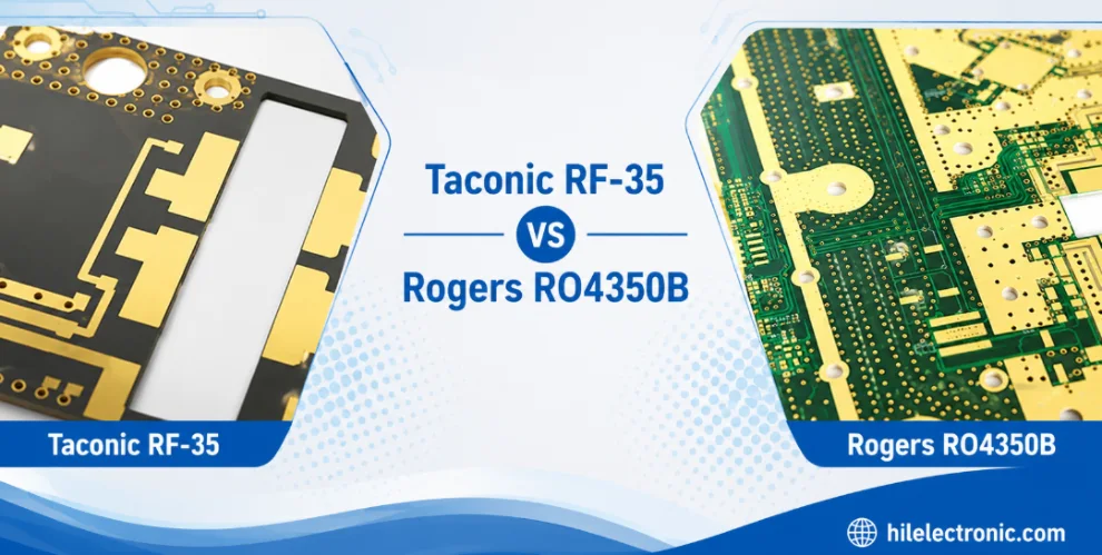
Taconic RF 35 vs RO4350B PCB
Table of contentsRF-35 vs RO4350B Procurement and...
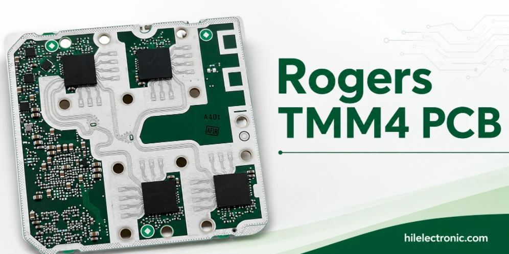
TMM4 Filter PCB Manufacturing
TMM4 filter PCB manufacturing is controlled by the...
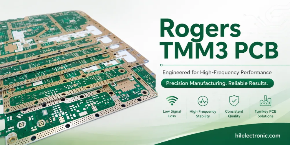
TMM3 PCB Manufacturing for RF Modules
TMM3 PCB manufacturing is most useful where the RF module...
TMM6 PCB Fabrication
TMM6 fabrication is the process-control page for a mid-Dk...
How to get a quote for PCBs
Let’s run DFM/DFA analysis for you and get back to you with a report. You can upload your files securely through our website. We require the following information in order to give you a quote:
-
- Gerber, ODB++, or .pcb, spec.
- BOM list if you require assembly
- Quantity
- Turn time
For PCBA services, please provide your BOM (Bill of Materials) and any specific assembly instructions. We also offer DFM/DFA analysis to optimize your designs for manufacturability and assembly, ensuring a smooth production process.