
Isola P25N PCB for No-Flow Bonding and Cavity Builds
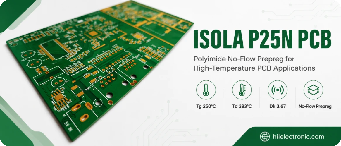
Isola P25N is a polyimide UL HB No-Flo® specialty prepreg. It is not a copper-clad laminate and should not be specified as though it replaces a core material. Its job is to create a controlled bond line in structures where normal prepreg flow would contaminate a cavity, cover a pad, flood a flex opening, disturb a heat-sink interface, or change a critical coplanarity.
Isola describes P25N as a high-temperature polyimide-based no-flow prepreg with minimal, uniform resin flow and adhesion to a wide range of materials, including flex films, treated or untreated copper, plated metals, and conventional laminate surfaces. The current product page lists typical Tg 250°C by DSC, Td 383°C, Dk 3.67 at 2 GHz, Df 0.0198 at 2 GHz, 0.5% moisture absorption, IPC-4101 /42, UL file E41625, and lead-free compatibility. Those properties define the material; the success of a P25N build is controlled primarily by bond geometry and process.
Why Standard Prepreg Fails Around Cavities, Heat Sinks, and Flex Openings
Conventional prepreg is designed to soften, flow, fill copper topography, displace air, and cure. That behavior is beneficial in an ordinary multilayer. It becomes a defect mechanism when the laminate contains a cavity, exposed die attach area, metal heat spreader, flex tail, optical opening, sensor recess, connector keep-out, or mixed-material interface.
| Structure | What normal flow can do | Resulting risk |
|---|---|---|
| Die cavity or component recess | Resin migrates across the cavity boundary or onto attachment pads. | Contamination, reduced clearance, die-height error, poor wire bond or attach surface. |
| Heat-sink/heat-spreader bonding | Resin redistributes unevenly under pressure and copper topography. | Bond-line thickness variation, voids, coplanarity error, higher thermal resistance. |
| Rigid-flex transition | Resin enters the flex window or onto coverlay/flex tail. | Stiffening, cracking, contamination, reduced bend life, dimensional interference. |
| Direct chip attachment | Resin covers lands or leaves an uneven attachment plane. | Assembly yield loss, poor contact, tilt, underfill or wire-bond problems. |
| Optical/RF cavity | Resin fillet changes a controlled opening or field boundary. | Optical obstruction, RF detuning, contamination, inspection failure. |
| Mixed-material stack | Different surfaces and CTEs create nonuniform wetting and pressure. | Local voiding, weak adhesion, warpage, edge lift. |
A no-flow prepreg is selected because the resin movement must be constrained, not because flow is undesirable everywhere. P25N still has to wet the surfaces and fill their micro-roughness. If the construction does not provide enough resin or pressure, the same no-flow behavior that protects a cavity can cause starvation or voids.
The geometry creates the process window
A flat coupon with uniform copper is an incomplete qualification for a recessed heat sink or cavity board. Local copper percentage, step height, cavity-wall plating, edge radius, surface finish, metal flatness, and tool compliance change pressure and resin movement. The process trial must reproduce the actual local geometry or a conservative test vehicle.
P25N Is a Bonding Prepreg, Not a Stand-Alone Laminate
The finished assembly normally combines P25N with rigid cores and flex materials, metal parts, plated surfaces, or prebuilt subassemblies. Because P25N is a prepreg, a drawing should identify where it is used, how many plies, which glass style, the target cured bond-line thickness, and which materials it bonds.
| Identity item | Correct callout | Incorrect shortcut |
|---|---|---|
| Material form | Isola P25N no-flow polyimide prepreg. | “P25N laminate” or “P25N core.” |
| Role | Bonding layer between named subassemblies or surfaces. | Generic dielectric layer with no interface definition. |
| Construction | Glass style, ply count, orientation, panel/roll form, target cured thickness. | Brand name only. |
| Interface | Surface A and surface B, finish, roughness/cleaning, local topography. | “Bond to metal” with no alloy or finish. |
| Restricted area | Cavity/keep-out boundary, allowed resin fillet, cleanliness limit. | “No resin in cavity” with no inspection tolerance. |
| Process | Storage, layup time, pressure/temperature/vacuum window, cool-down. | “Use supplier standard cycle.” |
Isola’s product page notes that no foil is offered for P25N. This reinforces the material identity: P25N is purchased and processed as prepreg, not as a copper-clad core. If a procurement system requires a laminate family field, the RFQ should still distinguish the P25N bond ply from the surrounding laminate system.
Freeze the Bond Geometry Before Tooling
The bond design must be frozen before tooling because cavity masks, prepreg cutouts, press pads, caul plates, dams, tooling pins, and inspection sections depend on the geometry. The following variables should be agreed by design, fabrication, assembly, and the material supplier.
| Variable to freeze | Why it affects the bond | Required drawing/RFQ output |
|---|---|---|
| Bond area and perimeter | Controls total resin demand and escape path. | CAD-defined bonding polygon and edge/cavity boundaries. |
| Step/cavity depth | Changes pressure distribution and required cured thickness. | Nominal and tolerance, local cross-section drawing. |
| Glass style and ply count | Set resin volume, reinforcement, flow, and bond-line thickness. | Exact style, number of plies, orientation and substitution rule. |
| Target bond-line thickness | Affects coplanarity, thermal resistance, cavity depth, and stress. | Nominal, tolerance, and measurement locations. |
| Copper topography | Consumes resin and changes local pressure. | Copper percentage/map, copper thickness, balancing or fill assumptions. |
| Surface materials and finishes | Influence wetting and adhesion. | Alloy/laminate, plating/finish, roughness/cleaning and age limits. |
| Allowed fillet or intrusion | Defines the real no-flow acceptance window. | Maximum distance/height/area and inspection method. |
| Warpage/coplanarity | Controls assembly and mechanical fit. | Datums, measurement condition, before/after lamination limits. |
Do not choose ply count from thickness alone
Ply count also changes the amount of resin available for wetting and filling. One thicker-looking glass style and two thinner plies may produce different flow, air escape, conformity, and local resin distribution. The choice should be proven by a trial that measures bond-line thickness, voids, fillet, adhesion, and cavity cleanliness.
No-Flow Does Not Mean Zero-Flow
“No-flow” is a process classification, not a promise of zero resin motion. The resin must soften and wet the mating surfaces. Pressure, temperature, heating rate, dwell time, vacuum, glass style, storage condition, copper density, and surface energy determine how far it moves and whether air escapes.
| Process variable | Too low/too little | Too high/too much |
|---|---|---|
| Temperature/dwell | Incomplete wetting or cure, weak adhesion, voids. | More resin movement, thermal stress, possible material degradation or excessive squeeze. |
| Pressure | Poor contact, incomplete conformity, trapped voids. | Resin intrusion, starvation, print-through, metal or board distortion. |
| Heating rate | Uneven temperature and late wetting; trapped volatiles. | Rapid viscosity drop before air escape; localized flow. |
| Vacuum | Trapped air and volatiles. | Vacuum alone cannot correct poor vent paths or insufficient resin. |
| Resin volume/ply count | Starved bond, unfilled topography, voids. | Excess fillet or intrusion, thicker bond line, dimensional shift. |
| Surface roughness | Low mechanical interlock or poor wetting if too smooth/contaminated. | Excessively aggressive roughening can trap contamination or reduce thin-metal integrity. |
The process window should be defined by both upper and lower acceptance limits. A result with no visible cavity intrusion but weak adhesion is not a successful no-flow process. Likewise, a strong bond with unacceptable resin on a die pad is not successful. The trial must show a region where all requirements are met simultaneously.
Build a Lamination Trial Around the Real Topography
A lamination trial should use the actual or conservative topography. The objective is not to discover one press recipe by trial and error; it is to understand which variables control the window and to create measurable production limits.
- Confirm incoming material. Verify P25N lot, glass style, resin content/construction, storage temperature, shelf life, package integrity, and out-time.
- Prepare representative surfaces. Use the actual copper, nickel, solder, metal, flex film, coverlay, or laminate finish with the production cleaning and age.
- Build a geometry test vehicle. Include the largest cavity, smallest bond land, highest copper step, longest flow path, sharpest corner, and critical coplanarity.
- Run a controlled design of experiments. Vary pressure, heating rate, peak/material temperature, dwell, vacuum timing, and ply count within supplier guidance and factory capability.
- Measure both sides of the window. Record intrusion/fillet, cured thickness, void area, wetting, adhesion, warpage, and surface cleanliness.
- Select a center process. Choose a recipe with margin from both starvation and excessive-flow limits, not the visually best single sample.
- Repeat across panels and lots. Confirm reproducibility before production tooling is released.
Use material temperature, not only press-platen temperature
The resin responds to its own temperature. Thick metal inserts, heavy copper, large panels, or asymmetric stacks can lag the platen. Thermocouple or equivalent characterization on the trial vehicle helps determine the real heating rate and dwell at the bond line. The production record should reference the qualified material-temperature window.
Tooling is part of the process
Caul plates, release films, pressure pads, dams, frames, and local shims influence pressure and resin escape. Their material, thickness, reuse condition, and placement should be controlled. A change in compliant pad or release system can alter the cavity fillet even when the press recipe is unchanged.
Surface Preparation and Adhesion to Unlike Materials
P25N is promoted for adhesion to a wide range of materials, but “adhesion to metal” is not one condition. Untreated copper, oxide-treated copper, ENIG, tin, solder, nickel, aluminum, stainless steel, polyimide film, coverlay, and conventional laminate surfaces have different chemistry, roughness, contamination, and thermal expansion.
| Interface | Preparation questions | Acceptance evidence |
|---|---|---|
| Copper or treated copper | Is the surface oxide/treatment compatible and within age? Is it clean and dry? | Peel or lap-shear method appropriate to geometry; cross-section and thermal exposure. |
| Nickel/plated metal | Which plating, thickness, passivation, age, and cleaning are present? | Bond-strength test on the exact finish and surface preparation. |
| Aluminum/heat spreader | What alloy, oxide state, roughness, flatness, cleaning and pretreatment are used? | Flatness, cleanliness, adhesion, void and thermal-cycling results. |
| Polyimide flex film/coverlay | Is the surface treated, plasma-cleaned, abraded, or chemically prepared? | Peel, flex transition inspection, bend-life or thermal cycling as applicable. |
| Conventional laminate surface | Copper density, solder mask, oxide, release contamination, and cure state? | Cross-section, adhesion, delamination/thermal-stress test. |
Surface preparation should be specific and time-limited. “Clean before bonding” is not enough. Define the cleaning chemistry or approved process, rinse/dry, plasma or abrasion if used, maximum hold time, handling gloves, and contamination controls. The trial should include the maximum allowed surface age.
Diagnose Resin Migration, Starvation, Voids, and Coplanarity
The most common defects are related. Resin that moves too far can leave another area starved. A thick copper step can block pressure and trap a void. A metal insert that is not flat can create both excessive squeeze at one edge and insufficient contact at another. Diagnosis should use the as-built cross-section and process record rather than the material name alone.
| Defect | Likely contributors | Corrective direction |
|---|---|---|
| Resin migration into cavity | Excess resin, pressure, dwell, heating rate, poor dam/cutout, low-viscosity window too long. | Reduce resin volume or pressure within qualified limits, improve tooling/cutout, shorten/shift flow window, verify material condition. |
| Bond-line starvation | Too little resin, excessive squeeze, long escape path, high copper topography, overpressure. | Increase appropriate ply/resin volume, rebalance pressure, reduce escape, revise topography or bond land. |
| Voids | Trapped air, insufficient vacuum/vent, poor wetting, contamination, abrupt step, low pressure. | Improve layup/venting, surface preparation, vacuum timing, conformity, pressure/temperature window. |
| Coplanarity error | Uneven bond thickness, warped insert, pressure nonuniformity, copper imbalance. | Control insert flatness, tooling, local pressure, resin volume, stack symmetry and measurement datums. |
| Weak adhesion | Contamination, aged finish, inadequate surface preparation, insufficient wetting/cure. | Requalify surface treatment and hold time, confirm material temperature/dwell and bond strength. |
| Edge lift/delamination | CTE mismatch, weak edge wetting, stress concentration, moisture or incomplete cure. | Improve edge design, surface/bond process, moisture control, cool-down and environmental qualification. |
Do not fix a defect by changing only one visible variable
For example, adding pressure may remove a central void while increasing cavity intrusion and edge starvation. Adding a ply may improve wetting while raising bond thickness and warpage. Use a controlled experiment and evaluate all acceptance metrics together.
Cross-Section, Bond Strength, and Cavity-Cleanliness Acceptance
Inspection should be designed into the panel. Critical interfaces may be inaccessible after lamination, so witness coupons and sacrificial cross-section areas should reproduce the same bond land, cavity edge, copper density, and metal/flex interface.
| Acceptance item | Suggested method | What must be defined |
|---|---|---|
| Cured bond-line thickness | Metallographic cross-section or calibrated dimensional method. | Nominal/tolerance and exact measurement locations. |
| Cavity cleanliness/resin intrusion | Optical inspection, image analysis, profilometry where needed. | Maximum intrusion distance, area, height, contamination type, and sampling. |
| Voids | Cross-section, scanning acoustic microscopy, X-ray/CT where geometry permits. | Maximum void size/area/location and method resolution. |
| Adhesion/bond strength | Peel, lap shear, pull, or geometry-specific coupon. | Specimen, rate, temperature, aging/preconditioning, minimum and failure mode. |
| Coplanarity/flatness | CMM, optical metrology, surface plate/feeler, profilometry. | Datums, clamping condition, temperature, before/after process limits. |
| Thermal/environmental durability | Reflow, thermal cycling, humidity, storage, shock as required. | Profile, cycle count, inspection after exposure and electrical/mechanical criteria. |
The acceptance plan should distinguish destructive first-article qualification from routine production control. Routine production may use cavity visual inspection, thickness/coplanarity, process records, and witness coupons, while periodic qualification uses cross-section, acoustic imaging, and bond-strength testing.
When P25N Is the Wrong Choice
P25N is not automatically superior to a standard polyimide prepreg. It can be the wrong choice when the structure needs substantial resin flow to fill heavy copper or deep topography, when no restricted area exists, when a lower-temperature material system is more compatible, when the required bond-line thickness cannot be achieved with available constructions, or when the factory lacks a qualified no-flow process.
| Situation | Why P25N may be unsuitable | Alternative direction |
|---|---|---|
| Large resin-fill demand with no cavity keep-out | Minimal flow may leave voids or starvation. | Use a standard or controlled-flow prepreg sized for the copper topography. |
| Simple flat multilayer | No-flow adds process and material complexity without functional benefit. | Use the qualified laminate family’s matching prepreg. |
| Very low bond temperature required | P25N is a high-temperature polyimide system. | Select a bonding film/prepreg compatible with the components and thermal budget. |
| Uncontrolled or highly variable metal flatness | No-flow cannot compensate for large gaps. | Improve the metal/mechanical tolerance or use a compliant qualified bonding system. |
| Factory has no P25N history | Process window, tooling, and inspection may be immature. | Run a full trial/qualification or choose an established alternative. |
| RF structure requires very low bond-layer loss | P25N’s electrical loss may be unsuitable in a field-intensive region. | Use an RF-compatible bonding system and model the actual bond layer. |
Process-Centered RFQ and Change Control
A P25N RFQ must look like a process specification. It should include the local geometry, interface materials, target bond line, restricted areas, and acceptance method.
- Material: Isola P25N no-flow polyimide prepreg; exact glass style, ply count, form, lot traceability, storage and out-time.
- Assembly stack: names and drawings of every bonded subassembly, core, flex, metal, plating, finish, and copper topography.
- Bond geometry: CAD-defined area, cavities, cutouts, bond lands, step heights, edge radii, target cured thickness and tolerance.
- Flow acceptance: maximum allowed resin intrusion/fillet and minimum required wetting/fill.
- Surface preparation: cleaning, roughening/plasma/chemical treatment, maximum hold time, handling and dryness.
- Press process: qualified material-temperature/heating-rate/pressure/vacuum/dwell/cool-down window and controlled tooling materials.
- Inspection: cavity cleanliness, bond-line thickness, void criteria, coplanarity, adhesion, cross-section locations and sample plan.
- Environmental: reflow, thermal cycling, humidity, storage, shock, or other product-specific durability tests.
- Change control: no change to glass style, ply count, P25N source/lot rules, surface finish, cleaning, press pad, release film, tooling, or cycle without review and correlation.
The strongest P25N release includes a golden process record and a set of approved section images showing acceptable wetting, fillet, bond thickness, and cavity cleanliness. This gives production and quality teams a concrete reference and prevents “no-flow” from being interpreted as a vague visual expectation.
Manufacturer references and release notes
The manufacturer links below establish P25N’s identity as a No-Flo polyimide prepreg and provide the public property and processing references used here. Before release, procurement and the fabricator should obtain the controlled datasheet and processing-guide revisions applicable to the supplied roll, glass style, and storage condition.

Recommended Posts

TMM4 Filter PCB Manufacturing
TMM4 filter PCB manufacturing is controlled by the...

TMM3 PCB Manufacturing for RF Modules
TMM3 PCB manufacturing is most useful where the RF module...

TMM6 PCB Fabrication
TMM6 fabrication is the process-control page for a mid-Dk...

TMM10 PCB Manufacturing for Compact RF Designs
Table of contentsHow TMM10 Shrinks RF StructuresTMM10 vs...
How to get a quote for PCBs
Let’s run DFM/DFA analysis for you and get back to you with a report. You can upload your files securely through our website. We require the following information in order to give you a quote:
-
- Gerber, ODB++, or .pcb, spec.
- BOM list if you require assembly
- Quantity
- Turn time
For PCBA services, please provide your BOM (Bill of Materials) and any specific assembly instructions. We also offer DFM/DFA analysis to optimize your designs for manufacturability and assembly, ensuring a smooth production process.