
Panelization Requirements for SMT Assembly

Table of Contents
At Highleap Electronics, we optimize panel designs for throughput, yield, and reliable depaneling. If you are reviewing broader layout rules that impact printability, placement accuracy, and inspection stability, start with our PCB assembly design rules before you freeze the panel drawing.
When SMT panelization is required
Why panelization matters for SMT
SMT equipment is designed to run stable, repeatable workpieces. A panel acts as a controlled carrier that moves through stencil printing, pick and place, reflow, and inspection with consistent clamping and consistent references. This reduces manual handling, improves alignment repeatability, and helps maintain a stable process window in production.
Typical situations that need a panel or handling rails
- Small boards that are difficult to convey or clamp as singles
- Automated production where printing and placement require stable references and handling edges
- Thin boards or assemblies with large heavy or tall components that increase warpage risk
- Edge dense designs where separation stress can damage sensitive parts
- Volume builds where panel processing reduces cost per unit by improving line utilization
What to define before you lock the panel
- Conveyor and support strategy including which edges need rails and how the panel will be supported during printing and reflow
- Alignment strategy including panel fiducials and any local fiducials for fine pitch placement
- Depaneling method and the keepout rules needed to protect components near the edge and near separation lines
If you want the fastest path to a manufacturable panel, align constraints early with a DFM pass. Highleap offers a free DFM review that can include panelization feedback before you release files for fabrication.
Panel layout and panel size planning
How to select a practical panel size
Panel size should be chosen to match your assembler equipment capability and support tooling, not only to maximize the number of boards per panel. Oversized panels can increase warpage risk and reduce printing consistency if underside support is insufficient. The best panel is the one that runs reliably on the line with stable printing, stable placement, and predictable reflow behavior.
Array configuration
Standard array is the preferred option for production.
- One design repeated across the panel
- Simpler programs and more consistent inspection settings
- More stable yield and easier process control
Mixed array is mainly for prototypes or early builds.
- Multiple designs share a panel to reduce setup or bare board cost
- Only recommended when the boards share compatible fabrication specs
- Requires careful programming and inspection planning
Orientation rules that help SMT stability
- Keep a consistent conveyor direction and define the panel datum orientation clearly
- Align connectors and critical parts consistently to reduce recipe variation and inspection ambiguity
- Distribute heavy and tall parts to avoid local sag and placement shift during reflow
- Maintain thermal balance by avoiding extreme copper imbalance across the panel when possible
If your design contains fine pitch parts and you are tuning paste release, aperture reductions, or step stencils, reference our stencil aperture guidelines while you finalize the panel layout and support plan.

Rails fiducials and tooling features
Rails provide the handling area used by conveyors and fixtures and also host panel features such as fiducials, tooling holes, and identification marks. Keep the rail region free of components and avoid placing fragile copper features where conveyor clamps or support pins may contact the panel. If you prefer a checklist driven handoff process, use our DFM checklist to confirm the panel and assembly package are complete.
Rail strategy
- Use rails on two opposite edges for stable conveyor transport in most cases
- Use rails on all four edges for very small boards, thin boards, or builds with higher warpage risk
- Ensure the rail width is sufficient for clamping and for placing fiducials and markings without interference
Tooling holes
Tooling holes are mechanical references for fixtures and setup repeatability. Because factory fixture standards vary, confirm the preferred hole size and placement rules with your assembler. Keep them consistent across revisions and keep them away from separation paths and weak edge regions.
- Prefer non plated tooling holes unless your assembler specifies otherwise
- Use two holes to define X and Y and consider an asymmetric feature pattern for error prevention
- Place holes in the rails where they remain intact through SMT processing
Panel fiducials and local fiducials
Fiducials are optical references used by placement machines and inspection systems. A robust fiducial implementation is consistent in shape, clean in its keepout area, and placed where it will not be removed by depaneling.
- Panel fiducials use at least three and place them asymmetrically in the rails
- Keepout cleanliness keep the fiducial area free of silkscreen, mask artifacts, and nearby copper patterns
- Local fiducials add them when fine pitch placement requires higher local alignment accuracy
Identification and traceability
- Panel part number and revision
- Date code or lot code location
- Orientation indicator where needed
- Board position labeling or bad board marking space for AOI feedback
Depaneling methods and reliability keepouts
Depaneling affects both cosmetics and reliability. The wrong method or insufficient keepouts can create separation stress that damages MLCCs, BGAs, edge connectors, and solder joints. Select the depaneling strategy early and design the panel around it. To avoid delays during NPI, include the panel strategy in your assembly handoff using our assembly file requirements as the reference checklist.
V score depaneling
V score is best for straight line separation on rectangular designs. It is efficient and produces clean edges, but it can introduce bending stress during separation if the process is not controlled. Use V score only when the board outline and separation lines are straight and when component keepouts can be enforced.
- Best for rectangular boards with straight separation lines
- Requires keepouts near score lines for stress sensitive components
- Controlled depaneling equipment is preferred over manual snapping for higher reliability builds
Tab routing depaneling
Tab routing supports irregular outlines and allows you to place tabs away from sensitive edge components. It often reduces stress compared with breaking a scored panel, but tab remnants may require finishing if edge cosmetics are critical.
- Best for irregular shapes, cutouts, and edge dense layouts
- Tab placement can be engineered to avoid connectors and sensitive parts
- May require secondary edge finishing depending on cosmetic requirements
Mouse bites for breakaway tabs
Mouse bites are perforations used on routed tabs to reduce separation force and improve manual break behavior. The best drill size and spacing depend on thickness, material, tab geometry, and depanel tooling. Validate the pattern in the first build and then keep it consistent for production.
How to choose the right method
- Choose V score when the board is rectangular, you need clean edges, and keepouts are feasible
- Choose tab routing when the outline is irregular, edge components exist, or stress control is critical
- For high reliability builds, prioritize low stress depaneling and conservative keepouts over maximum panel density
If you want a fast engineering review, share your Gerbers, BOM, and placement file and we can recommend a panel approach that matches your SMT line constraints and reliability targets. Before release, confirm your layout and outputs against our PCB assembly design rules so the full package is production ready.
Helen supports international engineering teams with end-to-end PCB fabrication and assembly solutions, helping projects move from quick-turn prototypes to stable mass production. Her experience spans high-frequency and RF boards, complex multilayer stackups, rigid-flex, and flex PCB technologies across multiple industries. By translating technical requirements into practical manufacturing plans, she helps customers improve manufacturability, reduce risk, and optimize cost and lead time—while maintaining consistent quality at scale.
at Highleap Electronics

Recommended Posts

Wireless Mechanical Keyboard PCB Manufacturing
Table of contentsWireless Keyboard PCB Procurement...

Split Keyboard PCB Manufacturing & Assembly
Table of contentsSplit Keyboard PCBA Procurement...
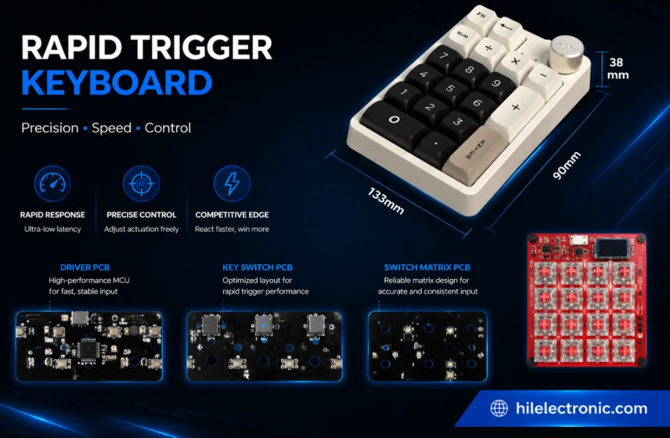
Rapid Trigger Keyboard PCB Manufacturing & PCBA
Table of contentsRapid Trigger PCBA Buying and Performance...
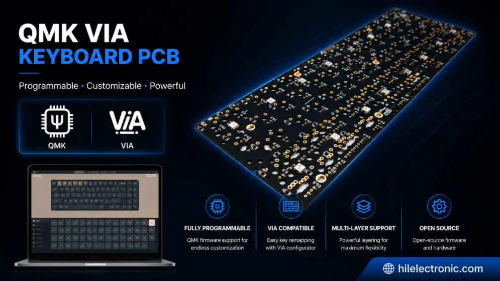
QMK/VIA Keyboard PCB Manufacturing & Assembly
Table of contentsQMK/VIA Keyboard PCB Buying...
How to get a quote for PCBs
Let us run DFM/DFA analysis for you and get back to you with a report.
You can upload your files securely through our website.
We require the following information in order to give you a quote:
-
- Gerber, ODB++, or .pcb, spec.
- BOM list if you require assembly
- Quantity
- Turn time
In addition to PCB manufacturing, we offer a comprehensive range of electronic services, including PCB design, PCBA (Printed Circuit Board Assembly), and turnkey solutions. Whether you need help with prototyping, design verification, component sourcing, or mass production, we provide end-to-end support to ensure your project’s success. For PCBA services, please provide your BOM (Bill of Materials) and any specific assembly instructions. We also offer DFM/DFA analysis to optimize your designs for manufacturability and assembly, ensuring a smooth production process.