
Split Keyboard PCB Manufacturing and Assembly: Lessons from KLOR
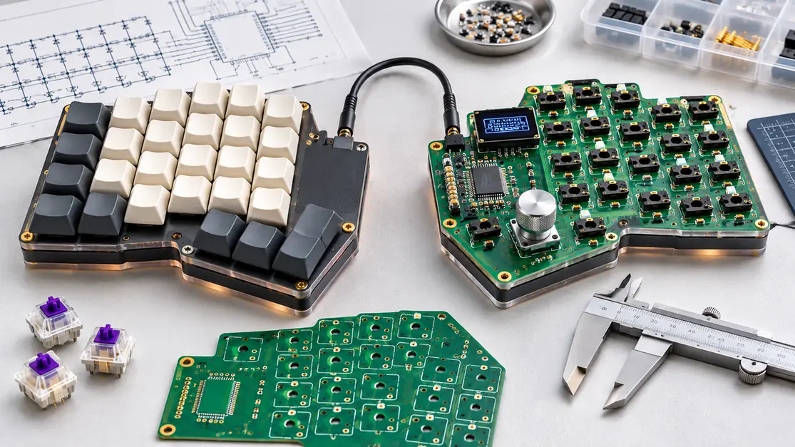
Figure 1. Original conceptual product illustration showing an assembled keyboard half, a populated PCB and an unpopulated PCB. This is not a photograph or manufacturing drawing of KLOR or a Highleap customer project.
A split mechanical keyboard is an excellent example of a product that appears electrically simple but becomes surprisingly demanding when it moves from a hobby build to repeatable factory production. Two separate halves must use the correct components on the correct side, agree with the selected switch plate and enclosure, communicate reliably, and pass the same functional checks despite mirrored mechanics. Optional lighting, encoders, displays and alternative layouts add more combinations to the manufacturing package.
For an OEM keyboard brand, the critical question is not whether a set of open-source Gerbers can be ordered. It is how to release a controlled split keyboard PCB assembly so that each left and right PCBA can be produced, inspected, programmed and paired without assembly ambiguity.
This article uses KLOR, an open-source 36–42-key, column-staggered split keyboard by GEIGEIGEIST, as an engineering reference. The project is listed in the help-14 mechanical keyboard index and publishes KiCad files, Gerbers, case and plate files, wired and Bluetooth build guides and firmware references. KLOR is not made or endorsed by Highleap Electronics; it is an independently authored reference used to explain the decisions involved in split-keyboard manufacturing.
What this guide demonstrates is a manufacturing method, not a product-category limitation. Reversible board population, component orientation, electromechanical fit, configuration-specific BOM control and end-of-line testing also matter for industrial controllers, embedded devices, lighting boards and other custom electronics. Highleap Electronics serves PCB fabrication and PCBA projects beyond keyboards; the KLOR design is simply a transparent, public example for discussing those methods.
Looking for PCB manufacturing or PCBA support? Highleap Electronics provides PCB fabrication, PCB assembly and turnkey services for customer-defined electronic products. For a keyboard or any other PCB assembly, share the appropriate design revision, BOM, placement data, target quantity and required tests to discuss a project-specific quotation. If your files are restricted, agree on confidentiality terms before transmission.
1. Freeze the Actual Keyboard Variant Before You Buy PCBs
KLOR is not one immutable assembly. Its default configuration is called Polydactyl, while its other layouts are created using break-off sections. The reference build guide lists the following complete keyboard switch counts: 42 for Polydactyl, 40 for Konrad, 38 for Yubitsume and 36 for Saegewerk. These counts are specific to the documented build, not a universal rule for every split keyboard.
| KLOR reference variant | Switches across both halves | Why it changes the production order |
|---|---|---|
| Polydactyl | 42 | Full reference population and the default layout |
| Konrad | 40 | Different remaining board outline and LED chain condition |
| Yubitsume | 38 | Fewer installed switch positions and a different final outline |
| Saegewerk | 36 | Smallest documented layout with additional break-off areas |
A buying team should not send “KLOR keyboard PCB” as the only product definition. The manufacturing release should name the variant, case style, wired or BLE configuration, switch type, lighting option, module type and target revision. Those choices determine the finished outline, quantity of switches and sockets, component population and test fixtures.
The KLOR build guide also lists 44 1N4148W SOD-123 diodes for the 42-key build, and different quantities for the smaller variants: 42 for Konrad, 40 for Yubitsume and 38 for Saegewerk. In other words, diode population should not be calculated by blindly copying the switch count. Use the selected revision’s schematic and BOM, including any non-switch diode positions.
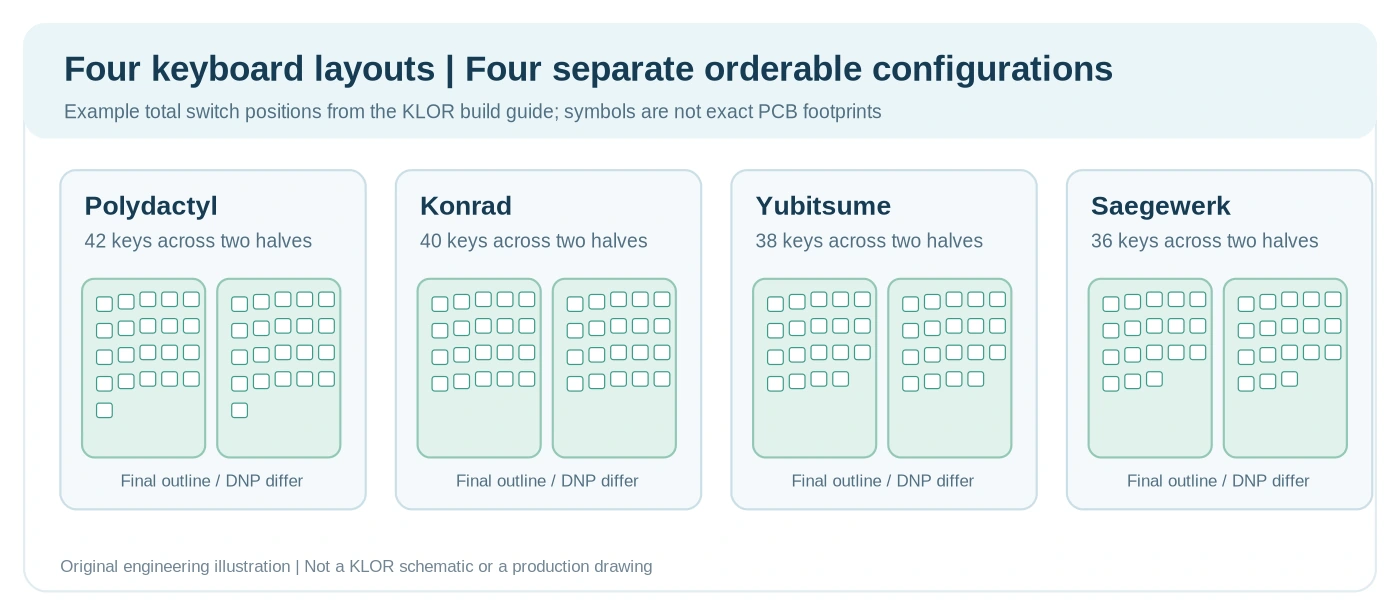
Figure 2. Original simplified layout-count comparison based on the documented KLOR variants. The silhouettes are schematic illustrations, not exact switch coordinates or official KLOR PCB contours. View the original KLOR project files.
Factory release gate: one orderable SKU must correspond to one fully defined left/right configuration. If several layouts will be sold, give each a controlled assembly option or SKU and a clear DNP list rather than asking the factory to infer the variant from a photograph.
2. Reversible Keyboard PCBs Require Side Specific Assembly Data
A distinctive KLOR design characteristic is its reversible PCB. The build guide warns that component mounting sides can change with the case type; a reversible bare board does not mean the same automated placement program can be reused unchanged for every assembled half. This is a much more consequential manufacturing problem than it might appear.
For PCB assembly, top and bottom are definitions from the released CAD files. For the finished product, left and right identify how the board appears in the enclosure. These are not interchangeable terms. A mirrored assembly can require a different connector orientation, reset-button location, controller mounting side or LED rotation.
A manufacturing engineer should review the following before stencil fabrication:
- Assembly coordinate system: confirm CAD origin, rotation convention, side field and the intended left/right finished orientation. Verify that any bottom-side placement coordinates have been transformed correctly for the production system.
- Component population: create per-side BOM variants or assembly drawings that unambiguously identify which footprints are installed for each half. Mark absent locations DNP.
- Socket positioning: confirm that hot-swap socket openings, switch orientation and controller socket pins correspond to the correct face of the board.
- Connector reach: check the mounted TRRS jack, MCU module, reset switch, encoder and OLED against the corresponding case and plate.
- Identification: mark or label left, right, PCB revision, variant and assembly revision in manufacturing records. Do not rely on an operator remembering a visual distinction.
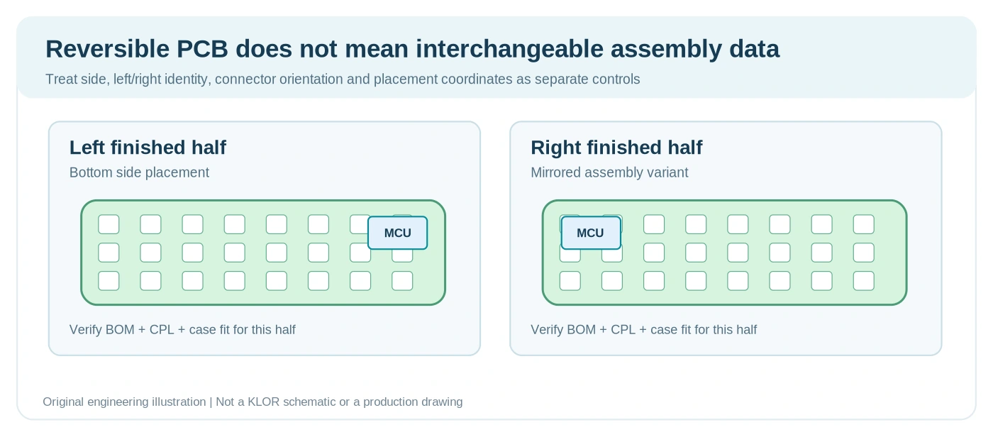
Figure 3. Conceptual explanation of a reversible keyboard PCB, two board faces and two finished assembly orientations. The diagram is not a reproduction of KLOR copper layers or its exact component placement.
The original build guide recommends checking the soldering guide even when using an interactive HTML BOM because the part side can differ. For an OEM build, translate that instruction into a controlled manufacturing drawing: a marked component-side view, variant-specific component placement files (CPL) and first-article photos. The goal is to prevent a beautifully soldered left half from becoming an unusable right half.
3. Break Off Layouts Turn PCB Routing into a Mechanical Quality Issue
KLOR obtains several layouts through removable PCB sections. That is convenient for an open-source kit, but it has production consequences. A break-off tab has to survive fabrication, handling, SMT processing and transport, yet separate cleanly without cracking the remaining board or damaging copper near the separation line.
The hobby guide describes cutting and breaking away unused sections with hand tools. For commercial manufacturing, the process should be evaluated for the actual tab geometry and final contour rather than copying a manual method indiscriminately. A factory may choose to remove optional sections before assembly, to use a controlled depanelization operation, or to revise the PCB panel design for SMT assembly if the production quantity justifies it.
During the PCB design for manufacturing review, check the minimum web width and residual tabs, plated holes and tracks near the break-off line, exposed FR-4 edges, enclosure contact points, and whether the resulting outline can be inspected consistently. A snapped board should never be accepted solely because it looks close enough to the expected shape.
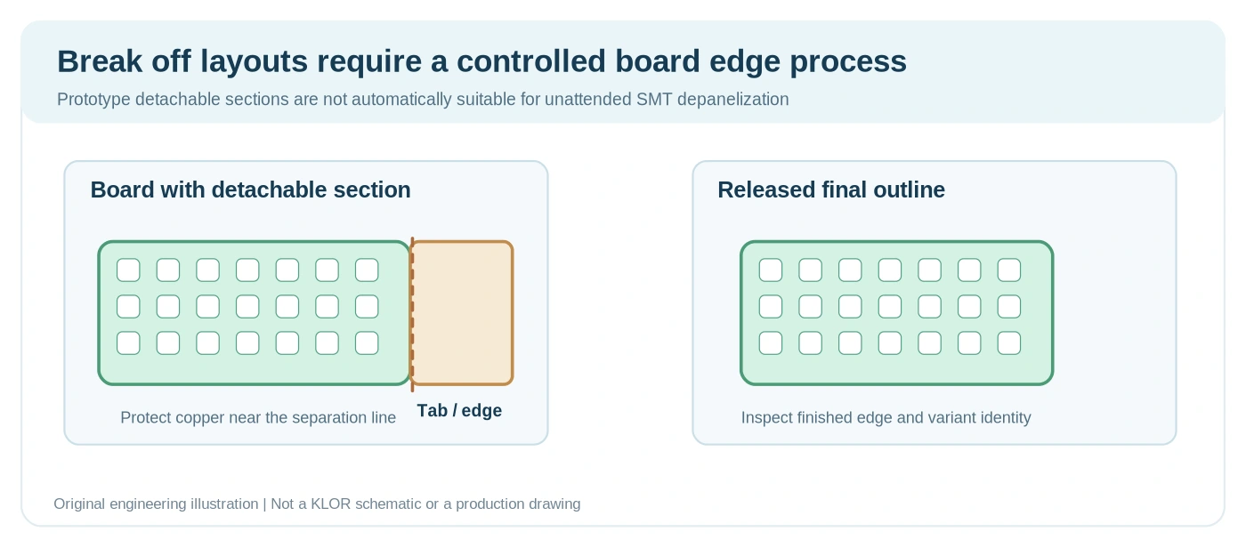
Figure 4. Illustrative comparison of prototype break-off features and a controlled factory separation plan. Exact tooling and edge tolerances require review of the customer’s board outline.
If a customer expects multiple KLOR variants, the quote should say whether the factory will deliver full reversible bare boards, partially removed PCB sets, or finished assembled variants. This affects material utilization, yield, inspection effort, packaging and the total cost for a split mechanical keyboard PCB order.
4. Hot Swap Sockets and Diodes Are the Core PCBA Quality Risks
The KLOR reference guide uses MX-compatible switch sockets and lists SOD-123 1N4148W diodes. For a keyboard PCBA supplier, the repetitive components may seem straightforward; however, board reliability depends heavily on small details repeated dozens of times.
Socket solder joints under mechanical load
Hot-swap sockets are soldered to the PCB so the user can install compatible switches later. That does not make the socket joints mechanically risk-free. Insertion forces pass through the switch pins and socket contacts. The factory must verify the exact socket manufacturer part number, approved pad layout, SMT stencil aperture, placement orientation, solder-fillet acceptance and board support.
A switch should be inserted with the board adequately supported, especially where no plate is holding the socket area flat. A socket with inadequate support can damage a pad even when the electrical joint initially passes continuity testing. Socket compatibility must be checked with the exact switch family and revision; “MX compatible” alone is not a complete mechanical drawing.
Diode orientation and traceability
The public KLOR soldering guide explicitly warns that the diode stripe must match the printed arrow on the PCB. For production, the authoritative reference should be the schematic, diode polarity in the assembly drawing and the manufacturer’s package marking. Silkscreen is helpful but does not replace an electrical netlist review.
The inspection and test program should detect an incorrectly placed diode and a missing switch circuit. A keyboard can connect to a computer and still have one nonfunctional key because of a single reversed diode or failed socket joint.
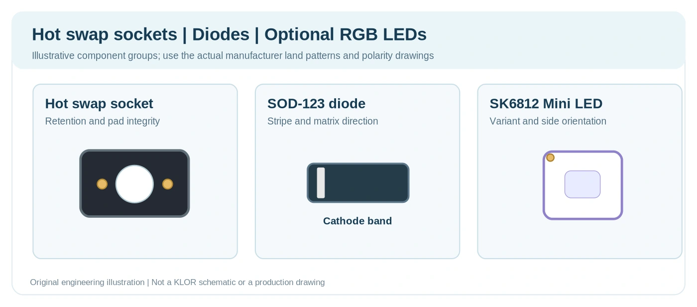
Figure 5. Original conceptual layout of a hot-swap socket, switching diode and optional RGB LED. It is not KLOR’s actual land pattern or manufacturing file.
For keyboard product developers
Planning a Hot Swap or Reversible Keyboard PCBA?
A design-specific PCBA review can clarify socket population sides, diode orientation, left/right BOM variants and assembly drawings before the first production run.
5. Per Key RGB Requires a Configuration Specific BOM and Test
The repository lists optional SK6812 Mini 3535 LEDs, expressly distinguishing Mini from Mini-E. The guide notes that the LED orientation is consistent within a half but differs between left and right. It also describes a jumper change for three-thumb layouts where the original LED chain would otherwise lose its starting point.
That creates three different factory release issues. First, the exact LED version must be identified by its manufacturer part number rather than a generic “SK6812” description. Second, the CPL must give the correct orientation on each side. Third, a layout-specific jumper or DNP condition must be documented so that a smaller variant does not have a broken LED chain.
Electrical testing should check the full chain from the first to last installed LED, not just whether the first few LEDs illuminate. Confirm color control, supply voltage, current consumption and uniformity using customer-approved test conditions. LED current and brightness depend on the implementation, so fixed current or lifetime promises should not be taken from a different keyboard.
The optional RGB feature also changes the commercial quotation: component quantity, LED source, soldering and inspection steps, programming and testing time may differ substantially from a no-RGB build. Separate the RGB and non-RGB BOM variants instead of hiding them in a general keyboard-PCBA quote.
6. Split Half Communication and the TRRS Connector Need Functional Tests
In the KLOR wired build, the two halves use a TRRS interconnect. The public 3D-printed-case guide lists two TRRS jacks and one cable; it also notes that a TRS cable can be used in a half-duplex configuration. The precise pin mapping and communication mode must come from the released firmware and schematic.
The PCB assembly review should check jack footprint, mechanical retention, solder-joint geometry, case clearance, left/right orientation and the electrical mapping for all conductors. The functional test should verify both halves through the intended cable and host configuration, including the keys on the secondary half.
As a cautious operating procedure, follow the product designer’s power and connection guidance when plugging or removing a TRRS cable. Do not assume that every split-keyboard jack design is hot-plug-safe. A conductive TRRS plug can briefly bridge contacts during insertion; the real risk depends on the interface wiring and protection design.
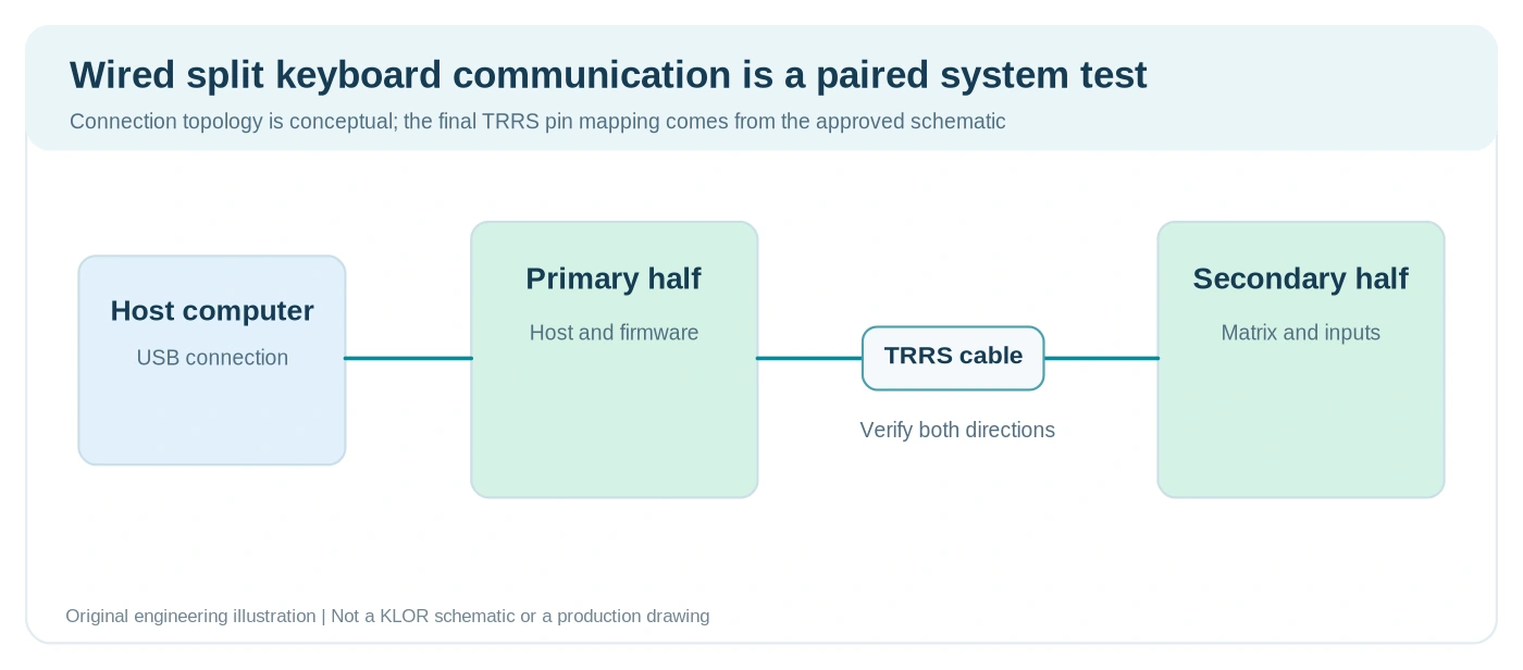
Figure 6. Conceptual wired split-keyboard link showing the host-connected primary half, inter-half cable and secondary half. It does not claim the exact KLOR contact pinout.
A factory test report for an inter-half cable should record the PCB revisions and firmware build, the tested cable assembly and the pass/fail result for each key on both halves. That is much more valuable to a keyboard brand than a generic “PCBA passed” stamp.
7. OLED Displays and Encoders Create Mechanical Clearance Challenges
The KLOR reference lists SSD1306 128 × 64 OLED modules and EC11 rotary encoders. These features can enrich a premium ergonomic keyboard, but their production risks are primarily orientation, header height and enclosure interference, rather than the difficulty of routing a handful of signals.
The guide warns that OLED modules can cover controller pins and can interfere with the switch plate if mounted too high. It recommends checking function before final OLED installation. For a production release, this suggests a disciplined sequence: verify MCU programming and key operation early, then install the display and mechanical parts, then repeat the functional test after complete assembly.
Key manufacturing checks include the approved OLED module’s dimensions and I²C address, connector/header height, exposed conductive surfaces, insulation strategy, switch plate clearance, encoder shaft height and knob-to-case interference. The exact display module may vary between suppliers even when its resolution and driver are described identically.
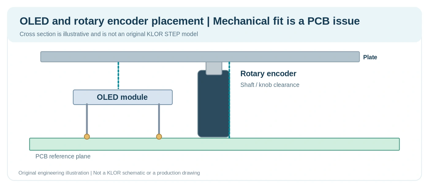
Figure 7. Original clearance-study illustration. Actual dimensions must be taken from the selected OLED, encoder, controller module, plate and enclosure drawings.
When ordering keyboard PCB assembly from Highleap Electronics, include an exploded 3D model or at least the STEP/DXF mechanical data for these interfaces. It is possible to manufacture a fully functioning PCBA that does not fit the final case unless the supplier understands these clearances.
8. Wired QMK and Bluetooth ZMK Are Different Manufacturing Configurations
KLOR publishes separate wired QMK and BLE ZMK build guides. The wired example can use a Pro Micro or compatible controller and a cable between halves. The wireless build guide instead specifies Bluetooth-capable controllers, individual batteries and power switches. These are not interchangeable BOMs.
The repository’s firmware listings include QMK configurations for several wired features and ZMK configurations for Bluetooth. However, not all optional hardware has complete support in every firmware configuration. In particular, the wired build guide describes optional trackball hardware while stating that trackball firmware was still to be added; the ZMK configuration also lists known limitations affecting the secondary-side encoder and trackball support. Do not market optional footprints as validated features before firmware acceptance testing.
For BLE production, the design owner should release the exact battery specification, connector polarity, charge/protection architecture, on/off switch circuit, controller module variant, antenna keep-out, firmware versions, pairing instructions and standby/sleep current acceptance limits. RGB lighting on a battery-powered board can significantly reduce runtime and should be evaluated against the product’s actual usage profile.
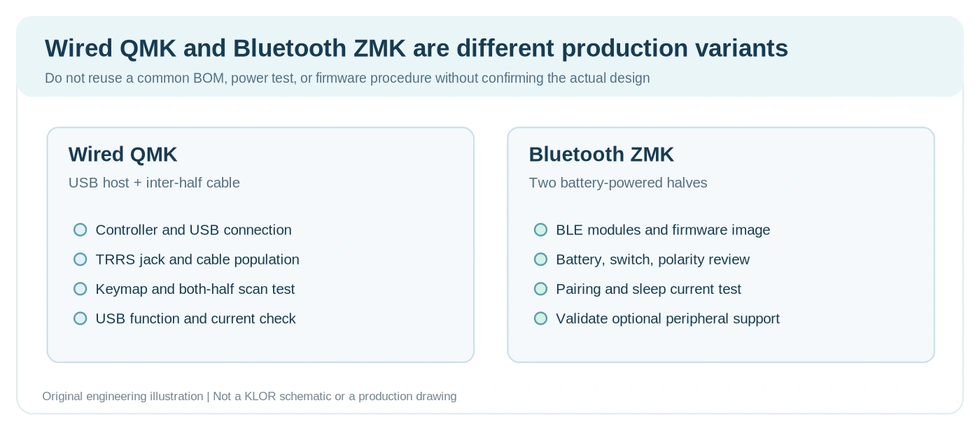
Figure 8. Original conceptual comparison of wired and BLE split-keyboard manufacturing packages. It is not a KLOR schematic or guarantee that every optional peripheral is firmware supported.
This is also why a low quoted PCB price is not the same as a complete product cost. A BLE variant adds sourcing, safety and end-of-line test requirements beyond the baseline wired design. Quote and test the two variants as different assemblies.
9. A Production BOM Must Capture Populated Side and Optional Features
A manufacturing BOM should be an unambiguous part-number list, not a shopping list copied from a hobby build page. The KLOR guide provides useful quantities and example components, but a commercial build still needs exact orderable MPNs, alternate approvals, reference designators, required revision, package and population side.
| Part or module | Published KLOR example | Release requirement for PCBA |
|---|---|---|
| Controller modules | Two Pro Micro class boards for the wired build | Exact controller MPN, firmware image, socket and polarity |
| Key switches / sockets | 42 positions in the Polydactyl reference | Layout-specific count and exact socket footprint |
| Switching diodes | 1N4148W SOD-123, 44 in the 42-key guide | Exact value, reference list, stripe/polarity and DNP status |
| RGB lighting | SK6812 Mini 3535, optional | Mini versus Mini-E distinction, side, orientation and chain jumper |
| Inter-half connector | Two TRRS jacks in the wired guide | Exact jack MPN, pin map, cable specification and mechanical support |
| OLED module | Two SSD1306 128 × 64 examples | Module source, I²C addressing, pinout and stack height |
| Rotary encoders | Two EC11 examples | Exact mechanical and electrical version, orientation and shaft length |
| BLE-specific items | Two compatible BLE controllers, batteries and power switches | Separate wireless BOM, battery polarity and power tests |
The numbers above describe the source build guide, not a Highleap stock list and not a substitute for a released customer BOM. If a company uses the KLOR concept to create a proprietary OEM keyboard, the electrical and mechanical release package should reflect the final designed product rather than the open-source prototype configuration.
10. Move from a Successful Prototype to a Repeatable Factory Pilot
A small batch of boards is a useful proving ground only when the build is measured. For split keyboards, the pilot should validate both halves as a set, rather than treating each populated PCB as an unrelated product. Use first-article inspection to confirm the assembly against the approved build data. The customer should define numeric thresholds and sampling for the acceptance plan below.
| Gate | Verification | Evidence retained |
|---|---|---|
| Incoming release | Correct PCB revision and variant-specific Gerber, BOM, CPL | Release checklist and approved package |
| Placement / solder | Diode polarity, hot-swap sockets, LEDs, jack, MCU sockets | First-article images, AOI or visual inspection records |
| Bare-board electrical | Short/open test of required connections | Fabrication test record |
| Firmware | Correct QMK or ZMK image, proper left/right designation | Firmware ID and programming log |
| Split functionality | All keys on both halves, inter-half link, keymaps | Test report by left/right serial or lot identifier |
| Optional features | RGB order, OLED, encoder, haptic or audio only where supported | Feature-specific result and approved pass criteria |
| Wireless variant | Pairing, charge/power behavior, current consumption | BLE and power-test data |
| Mechanical fit | Plate alignment, connector access, clearances and screws | Assembly check and dimensional report |
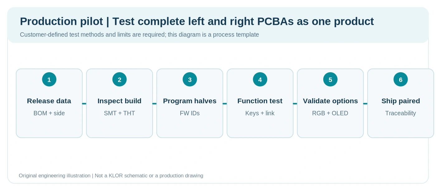
Figure 9. Original engineering test-flow template for paired split-keyboard assemblies. Pass/fail limits must be agreed for the customer design.
For repeated orders, trace the PCB revision, BOM revision, assembly variant, controller firmware and any approved component substitutions. A working left half and a working right half are not automatically a working pair if they contain mismatched firmware or incompatible hardware revisions.
11. What Split Keyboard PCB Engineering Teaches About Other Electronic Products
A split keyboard is a convenient public test case for several common electronics manufacturing problems. It should not be treated as evidence that Highleap Electronics only builds input devices. The same production disciplines matter whenever a product contains multiple PCB revisions, optional components, user-facing connectors, indicator LEDs or programmed control electronics.
For OEM teams in any industry: the useful takeaway is how to turn an evolving hardware design into controlled, manufacturable documentation. Highleap can discuss bare PCB fabrication, component sourcing and PCBA, and turnkey assembly options according to the actual project scope, not according to the application used in this educational example.
The fabrication and assembly requirements still depend on the final product. A keyboard example cannot validate a medical, automotive, safety-critical or industrial controller design by analogy. Each PCB requires a fresh review of applicable standards, materials, component availability, reliability and test requirements.
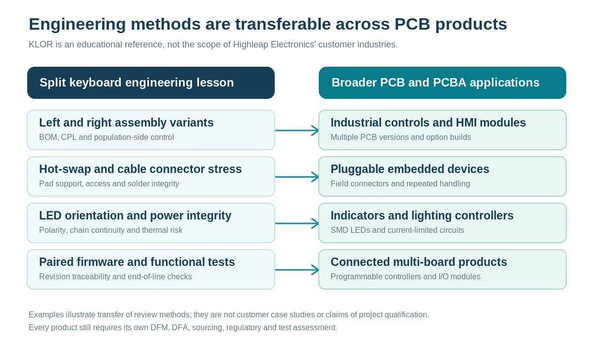
Figure 10. Original engineering comparison. These are examples of transferable design review methods, not verified Highleap customer projects or qualification claims.
| Lesson illustrated by the public KLOR design | Related electronics manufacturing use | What an OEM customer should provide |
|---|---|---|
| Left/right reversible board population and distinct DNP options | Industrial HMI panels, matched controller boards and region-specific product variants | Variant matrix, revision-controlled BOM, side-specific CPL and assembly drawings |
| Hot-swap socket and interconnect mechanical loads | Pluggable embedded modules, service connectors and test interfaces | Exact connector MPN, mechanical envelope, insertion load and inspection criteria |
| Addressable LED orientation and chain continuity | Status indicators, illuminated controls and lighting controllers | LED MPN, polarity map, power budget and functional test pattern |
| Display and encoder position relative to the enclosure | Embedded control panels and instrument interfaces | STEP/DXF, component height envelopes, tolerance stack and final assembly specification |
| Wired/BLE differences and paired-board firmware release | Connected sensor devices and multi-board embedded products | Separate BOMs, module specifications, firmware release, test plan and product acceptance limits |
Beyond keyboard electronics
Have an Industrial or Embedded Electronics PCB Project?
The same design-release, SMT assembly and quality-control principles apply to many other electronic products. Highleap provides PCB fabrication and PCBA services beyond mechanical keyboards.
12. Public Open Source References and Confidential Customer Designs
This article analyzes independent, publicly accessible KLOR materials; it does not showcase a customer-supplied PCB design. That distinction is important for both intellectual property rights and customer trust. An open repository provides a transparent engineering example, but being visible on GitHub does not eliminate copyright or license obligations. The KLOR repository contains a GPL-3.0 license; separate permissions for photographs and other media should be verified before reproducing them in a commercial article.
Our editorial distinction is straightforward: the KLOR example is an independent source for discussing PCB fabrication, surface-mount assembly and testing. Customer drawings and prototype photographs are not public demonstration assets by default. A customer case study requires explicit permission from the rights holder and a separate factual review.
For a customer with commercially sensitive material, the practical step is to agree on NDA, permitted file access and a suitable document-transfer process before sending restricted files. The actual obligations must be established through Highleap’s confirmed company procedures and the parties’ agreement; this article should not be read as a substitute for a signed confidentiality commitment.
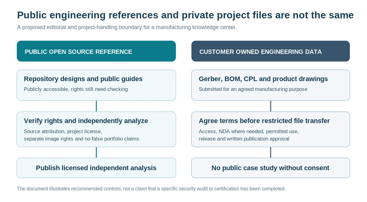
Figure 11. Recommended editorial and project-handling boundary. The diagram is a proposed control framework, not evidence of a completed security audit, certification or specific contractual guarantee.
| Public engineering reference used in this article | Private customer engineering project |
|---|---|
| GitHub repository, public build guide and independently created technical diagrams | Customer-owned Gerber, BOM, CPL, firmware, PCB images, test data and commercial plans |
| Discussed with attribution and clear limitations on what is actually verified | Provided for the manufacturing and engineering purpose agreed with the customer |
| May be published only when the relevant use is permitted by the applicable rights and license | Should not be reused in public case studies, articles or promotional images without prior written authorization |
| Never represented as a Highleap manufacturing record or client portfolio item | Access, retention, subcontractor use and NDA requirements should be settled under actual project terms |
13. How to Request PCB Fabrication and PCBA Quotes for Any Custom Electronics Project
Highleap Electronics is a PCB fabrication and PCB assembly service provider, not a keyboard-only manufacturer. Whether a customer is building an ergonomic keyboard, an embedded controller, an industrial interface or another electronic assembly, the quotation should define what is to be delivered: bare boards, partial PCBA, programmed and tested PCB assemblies, or a wider turnkey scope. The engineer should review the specific design files, component availability, assembly complexity and acceptance criteria before confirming feasibility.
Highleap Electronics publishes PCB fabrication, PCB assembly and keyboard PCB manufacturing services. Its published PCBA scope includes component sourcing, SMT/DIP operations, first-article inspection and functional testing; the exact project scope is agreed after data review. The factory should be asked to confirm whether sockets, modules, connectors and any final product assembly are included in the specific quotation.
Send a Controlled Engineering Package for Review
- PCB data: Gerber or ODB++ files and NC drill or native KiCad/Altium sources for each required revision.
- Variant definition: left/right assembly designation, Polydactyl/Konrad/Yubitsume/Saegewerk or custom layout, wired/BLE, RGB/no-RGB, case style.
- BOM and CPL: exact manufacturer part numbers, all DNP locations, per-side placements and alternate rules.
- Assembly drawing: diode stripe, socket side, jumper settings, controller orientation, TRRS jack and OLED mounting instructions.
- Mechanical data: plate DXF/STEP, enclosure model, break-off policy, controller/display height and connector clearance.
- Firmware and testing: image files, controller type, keymap, left/right flash instructions and feature acceptance tests.
- Commercial inputs: sample quantity, production quantity, target schedule and whether parts are sourced by Highleap or supplied by the customer.
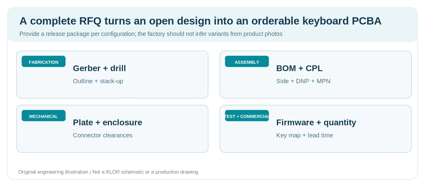
Figure 12. Original quotation-input checklist for left/right keyboard PCB sets. A complete package prevents errors in population sides, quantities and assembly requirements.
PCB FABRICATION & ASSEMBLY
Get a Quote for Your Split Keyboard PCB Assembly
Share the keyboard variant and target quantity, along with your fabrication files, BOM and placement data. Include any programming and functional test requirements so we can scope the quote.
Sending confidential design files? Agree on NDA terms and a file transfer method before sharing them.
14. Questions from PCB and Keyboard Hardware Teams
Can the same PCB be used for both left and right keyboard halves?
Sometimes. A reversible design such as KLOR can use a common bare-board concept, but the populated side, connector orientation, controller position, jumpers and case constraints still need a defined left/right assembly release. Reversibility does not remove assembly-control requirements.
Can a split mechanical keyboard use a two layer PCB?
Many keyboard matrices and controller-module designs can be implemented on two layers when the electrical, mechanical and routing requirements permit it. The actual KLOR production data should be checked before making any claim about the exact stack-up or copper thickness of a specific revision. There is no reason to specify extra layers solely because a keyboard has two halves.
Are hot swap sockets the same as soldered mechanical switches?
No. Hot-swap sockets remain soldered to the PCB, while compatible switches can be installed and removed from the socket contacts. Exact socket and switch specifications, solder-joint quality and mechanical support determine reliability.
Does the open-source KLOR project guarantee every optional feature works?
No. The project documents hardware options and firmware configurations, but its guides also note firmware limitations for certain peripherals. Verify the intended firmware build and each option at the prototype stage before promising it in an OEM product.
What does Highleap need to quote a pair of custom keyboard PCBAs?
Provide the fabrication data, target quantity, BOM with approved part numbers, per-side CPL, assembly drawings, variant/DNP information, mechanical drawings, firmware and the final test plan. State whether you require bare PCB pairs, assembled boards or fully programmed and tested PCBA sets.
Do the KLOR pictures prove Highleap manufactured this keyboard?
No. All images in this article are original conceptual illustrations rather than verified KLOR production photographs, and the open-source project belongs to its original creator. No KLOR design is presented as a Highleap customer build.
Will a customer design be published in a technical article?
Public open-source references and privately supplied design files are different sources of information. A customer-owned Gerber, BOM, PCB image, firmware or product photo should not be published or used in marketing without prior written permission from the rights holder. Customers with confidential files should contact Highleap to agree on NDA and permitted data handling before transfer; this article itself is not a confidentiality agreement.
Does Highleap Electronics manufacture PCB assemblies beyond mechanical keyboards?
Yes. Highleap publishes general PCB fabrication, PCBA services and turnkey assembly capabilities. This article uses a keyboard to explain selected manufacturing controls, not to define the range of electronics Highleap can review. Final feasibility always depends on the customer’s design and requirements.
Conclusion
The manufacturing lesson of KLOR is the discipline required to control variant, component orientation, mechanical interfaces, firmware and paired-board testing across a real release package. These same controls also matter for many other custom electronic products. Publicly documented hardware provides a transparent way to study these decisions without implying access to or disclosure of private customer designs.
Highleap Electronics provides PCB manufacturing and PCBA services for customer-defined designs. For a realistic quote, send the approved fabrication and assembly package, target quantity and test requirements. If the files are commercially sensitive, first agree on the applicable confidentiality and file-handling terms. Start a PCB or PCBA project with Highleap Electronics.
Source References and Image Attribution
- help-14 mechanical keyboard index — project discovery index.
- GEIGEIGEIST KLOR repository — original author, project scope, KiCad/Gerber links, layouts, case files and firmware references.
- KLOR 3D printed case build guide — layout BOM, reversible assembly, diode and LED notes, TRRS, sockets and OLED instructions.
- KLOR BLE build guide — Bluetooth controller, batteries, power switches and wireless assembly notes.
- KLOR QMK firmware configuration — wired feature and controller configuration.
- KLOR ZMK firmware configuration — wireless configuration and documented known limitations.
- KLOR repository license — GPL-3.0; verify the applicable license terms for specific files before reuse in a commercial product.
- Original KLOR project photos — reference images by the project author; not reproduced in this package because separate image reuse rights were not independently verified.
- Highleap PCB assembly services and Highleap keyboard PCB manufacturing — company service descriptions.
- GitHub documentation on repository licensing and default copyright — publisher reference used to separate public technical discussion from private manufacturing projects.
- Highleap PCB fabrication services — publisher reference used to separate public technical discussion from private manufacturing projects.
- Highleap turnkey PCB assembly services — publisher reference used to separate public technical discussion from private manufacturing projects.
Independence and confidentiality note: KLOR is an independent open-source design by GEIGEIGEIST. Highleap is not affiliated with or endorsed by the project author. All diagrams are original conceptual artwork and are not original KLOR schematics or verified Highleap factory photographs. Customer-provided production files are not source material for public technical posts without written permission. Confirm NDA and file-handling terms independently before sending restricted designs.

About the Author
Shirley Leung
PCB/PCBA Product Manager & Technical Sales Engineer
Shirley has 5 years of hands-on experience in PCB fabrication and assembly services. Her expertise includes complex multilayer boards, HDI structures, turnkey component sourcing, SMT assembly, testing, and full system integration.
As both a technical advisor and sales specialist, she supports customers with DFM guidance, cost optimization, and production planning, helping projects move efficiently from design to mass production with consistent quality and on-time delivery.
Recommended Posts
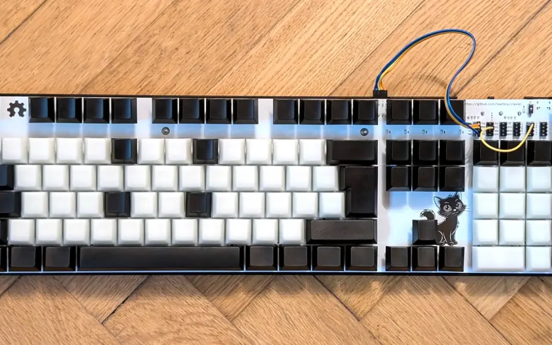
FPGA Mechanical Keyboard PCB Manufacturing and Assembly
Figure 1. Assembled Clavier reference keyboard. This is an...
IT-858G Automotive PCBs for Heavy-Copper Power Control
IT-858G PCB applications in automotive electronics and...
IT-958G PCB for High Speed Servers and Backplanes
IT-958G multilayer PCB examples for server and high-speed...
IT-968GSE PCB for High-Speed Networking
IT-968GSE PCB illustration for ultra-low-loss switch and...
How to get a quote for PCBs
Let‘s run DFM/DFA analysis for you and get back to you with a report. You can upload your files securely through our website. We require the following information in order to give you a quote:
-
- Gerber, ODB++, or .pcb, spec.
- BOM list if you require assembly
- Quantity
- Turn time
In addition to PCB manufacturing, we offer a comprehensive range of electronic services, including PCB design, PCBA, and turnkey solutions. Whether you need help with prototyping, design verification, component sourcing, or mass production, we provide end-to-end support to ensure your project’s success.
For PCBA services, please provide your BOM (Bill of Materials) and any specific assembly instructions. We also offer DFM/DFA analysis to optimize your designs for manufacturability and assembly, ensuring a smooth production process.