
Ortholinear Keyboard PCB Manufacturer | Custom Grid Layout
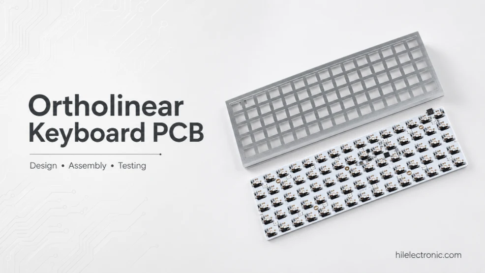
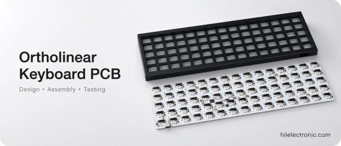
An ortholinear keyboard PCB manufacturer must preserve a precise grid while supporting the product’s compact matrix, layered keymap and optional controls. Ortholinear boards arrange keys in aligned rows and columns rather than the staggered pattern of a conventional keyboard, but the exact key count, spacing, thumb keys and enclosure still vary widely.
Highleap Electronics manufactures custom ortholinear keyboard PCBs as bare boards, hot-swap or soldered-switch PCBAs, programmed QMK/VIA or customer-firmware assemblies and compact wireless modules. Options can include per-key RGB, encoders, displays, USB-C and split or one-piece architectures.
Many ortholinear designs use two copper layers and place sockets, LEDs, diodes and controller parts on both sides. Copper-layer count and assembly-side count are separate. An initial quote can start from a grid size, reference image and quantity; no PCB schematic is required.
Start an Ortholinear Keyboard PCB Quote
Tell us the grid size or approximate key count, wired or wireless mode, quantity and whether you need bare PCB or PCBA. A photo, layout or existing files are optional. Highleap can begin with incomplete information and no schematic is required for the first quote.
Ortholinear Grid Layout, Use Cases and Procurement Requirements
Common products include 40% grid keyboards, Planck-style layouts, macro grids and customer-specific control surfaces. The production package should state row and column count, key pitch, optional 2U keys, encoder or display locations and whether the PCB is intended for a specific open-source case or a proprietary enclosure.
| Requirement | Why it changes the PCB | What to release |
|---|---|---|
| Grid size and pitch | Sets board outline and matrix density | Dimensioned coordinate drawing. |
| 1U/2U options | Changes stabilizer, switch and keymap positions | Variant assembly drawing and firmware map. |
| Controller format | Affects height, USB location and programming | Module/MCU MPN and mechanical envelope. |
| Case compatibility | Controls mounting holes and edge clearance | Enclosure or plate CAD, not only a product name. |
Ortholinear PCB Procurement Choices
Common purchasing questions are whether the board supports a 4×12, 5×12 or custom grid, whether switches are soldered or hot swappable, how thumb keys are handled and whether the controller is integrated or modular.
| Choice | Manufacturing effect | First-inquiry information |
|---|---|---|
| Grid dimensions | Determines board size, switch count, matrix and test fixture. | Rows × columns or a reference layout. |
| Key spacing | Affects switch center coordinates, keycap clearance and case fit. | Standard or custom spacing if known. |
| Controller | Integrated MCU and plug-in module differ in height, sourcing and programming. | Preferred firmware or wired/wireless requirement. |
| Options | Encoders, OLED, RGB and split links change routing and test. | List desired functions without needing final part numbers. |
Matrix Routing, Controllers and Firmware Options
A regular grid simplifies repeated placement but makes coordinate errors immediately visible. Switch-center pitch, board outline, mounting holes and plate openings should use one datum; a small accumulated error can misalign an entire row or column with the case.
Compact ortholinear boards can still be routing-dense once matrix traces, diodes, hot-swap socket systems, RGB power/data, USB, displays and controller modules compete for space. Two layers are often sufficient, while feature-heavy designs may benefit from additional layers. The decision should follow DFM, return-path and power-distribution review rather than a fixed layer-count target.
Optional 2U positions and multi-layout footprints must be documented by SKU so assembly, firmware and testing identify which positions are actually fitted.
Integrated MCU, Controller Module and Wireless Options
An integrated keyboard controller MCU reduces module height and connector count, while a removable controller module can simplify development and replacement. The module route introduces header/socket height, orientation, sourcing and mechanical-clearance requirements. Wireless modules also need antenna keepout and enclosure review.
| Controller approach | Advantages | Production controls |
|---|---|---|
| Integrated wired MCU | Low profile, fewer connectors, optimized BOM. | Programming pads, bootloader, USB and rework plan. |
| Plug-in controller module | Flexible development and replacement. | Header alignment, module orientation, height and module availability. |
| BLE module | Simplified wireless integration. | Antenna keepout, battery/charger, pairing and sleep-current test. |
| Chip-down wireless | Compact optimized product at volume. | RF layout, crystals, programming, certification and test access. |
Layers, Keymaps and Programmable Controls
Ortholinear products often depend on firmware layers because the physical key count is reduced. QMK/VIA, ZMK or customer firmware should be released with the matrix definition, bootloader and logical keymap for the same hardware revision.
- Match the physical grid to matrix coordinates.
- Identify thumb, layer and tap/hold keys in the production test map.
- Control firmware separately for each grid or option variant.
- Verify modifiers, layer switching, encoders, displays and recovery mode—not only basic key closure.
- Label removable controller-module orientation.
Switch, Socket, Plate and Enclosure Compatibility
Ortholinear boards may use MX, Choc or other low-profile keyboard switch systems. These are not interchangeable. Switch generation, hot-swap socket, plate opening, PCB thickness and keycap geometry must be approved as one stack. For low-profile builds, connector height, battery location and bottom-side sockets often dominate enclosure thickness.
| Integration risk | Typical symptom | Prevention |
|---|---|---|
| Grid/plate mismatch | Columns bow or switches bind. | CAD overlay and physical first-article fit. |
| Socket/standoff interference | PCB does not seat or sockets are loaded. | 3D bottom-clearance review. |
| Module height conflict | Case cannot close or USB opening is wrong. | Approve module/header stack and enclosure. |
| Keycap collision | Adjacent caps rub despite correct switch pitch. | Use intended keycap profile in pilot build. |
Ortholinear buyers often prioritize compact thickness. Socket height, controller module, USB connector, display, battery and enclosure standoffs must be reviewed together. Low-profile and MX-style systems are not interchangeable, and a hot-swap footprint should be approved against the exact socket and switch.
- Confirm switch pitch and plate openings.
- Check bottom-side socket clearance and foam compression.
- Control controller-module height and header orientation.
- Verify USB-C position against the case wall.
- Define board thickness and flatness where the case has limited support.
Fabrication, Assembly and Production Testing
Rectangular grid boards can panelize efficiently, which supports competitive prototype and volume pricing. However, large arrays contain many repeated holes and pads, so drill wear, registration and solder-mask alignment should remain controlled across the panel. Low-profile or reversible designs may use unusual footprints and require additional first-article checks.
Surface finish, solder-mask color and artwork can be customized. When the PCB is visually exposed, cosmetic acceptance should be defined separately from electrical acceptance. Highleap can provide batch discounts after the grid, controller, finish and order forecast are stable.
Ortholinear PCB Manufacturing, Testing and Quality Records
Keyboard PCBA functional testing should verify, including unused optional footprints that must remain unpopulated. For hot-swap boards, socket presence and representative insertion are added. RGB, display, encoder, USB/wireless and sleep current tests depend on the variant. A grid-based fixture can be efficient, but it must use the same coordinate origin as firmware.
The manufacturing route can include bare PCB electrical test, double-sided SMT where required, hot-swap socket or THT switch assembly, controller-module installation, firmware programming and full-key testing. A dedicated fixture is useful for dense grids because one missed key or rotated LED can be difficult to identify after the case is assembled.
- Verify PCB outline, mounting and grid pitch.
- Inspect repeated socket, diode and LED orientation.
- Program the correct variant firmware.
- Test every key and defined layer function.
- Verify USB, encoder, display and RGB features.
- Perform enclosure fit on the pilot when supplied.
Failure Diagnosis, Variants and Volume Supply
A complete column failing usually indicates a matrix net, controller pin or firmware issue; one failed key points toward the switch/socket, diode or local trace. A keycap grid that looks uneven may result from plate or switch-center tolerance rather than PCB electrical defects. For module-based designs, intermittent rows can come from header soldering or an incorrectly seated controller.
- Map failures by grid coordinate, not only printed legends.
- Check module and socket orientation before replacing the MCU.
- Test layer keys and chord behavior with released firmware.
- Inspect far-edge RGB and power rails under maximum approved load.
- Verify case mounting does not bend the center of a wide grid.
Niche Applications, MOQ and Variant Strategy
Ortholinear products serve compact keyboards, programmable macro grids, portable workstations and specialized control surfaces. Buyers usually value exact geometry, firmware flexibility and reliable prototype or low-volume production more than a generic “keyboard PCB” specification.
Unit cost improves when variants share the same PCB, controller, component family and fixture, but excessive optional footprints can increase assembly ambiguity and test risk. Each grid size, controller option and fitted layout should retain its own controlled BOM, firmware image and test map.
Ortholinear PCB Production Records
When required for the order, records can cover dimensional first-article results, plate or case fit, socket and switch inspection, firmware identification, every-key output, option-SKU labeling and final interface tests. Geometry and firmware records should reference the same sellable variant.
Ortholinear Keyboard PCB FAQ
What is an ortholinear keyboard PCB?
It is a keyboard PCB with keys arranged in aligned rows and columns, usually combined with programmable layers to support a compact physical layout.
Is ortholinear automatically ergonomic?
No. Some users prefer the grid, but ergonomic benefit depends on the complete layout and individual use.
Can an ortholinear PCB use hot-swap sockets?
Yes, provided the exact switch, socket, plate, pitch and enclosure clearance are validated.
Can one grid PCB support 1U and 2U keys?
Possible with overlapping footprints and firmware variants, but the assembly drawing and test plan must identify the selected configuration.
Discuss an Ortholinear Keyboard PCB
Share the grid size or reference layout, approximate quantity and required service. Existing files can follow after the initial discussion. Highleap does not require a PCB schematic to start the quotation.

Recommended Posts

Taconic RF-35 PCB Manufacturing Service — Prototype Through Volume Production
Figure 1. Taconic RF-35 PCBTaconic RF-35 is the workhorse...

Isola Astra MT77 PCB Manufacturing
Figure 1. Isola Astra MT77 PCB ManufacturingIsola Astra...

Nelco N4000-13 PCB Material and Manufacturing Guide | Highleap Electronics
Figure 1. Nelco N4000-13 PCBNelco N4000-13 PCB is a...

Copper Clad Laminate: Complete Material Selection Guide for PCB Engineers
Every electrical property that matters in a printed...
How to get a quote for PCBs
Let’s run DFM/DFA analysis for you and get back to you with a report. You can upload your files securely through our website. We require the following information in order to give you a quote:
-
- Gerber, ODB++, or .pcb, spec.
- BOM list if you require assembly
- Quantity
- Turn time
For PCBA services, please provide your BOM (Bill of Materials) and any specific assembly instructions. We also offer DFM/DFA analysis to optimize your designs for manufacturability and assembly, ensuring a smooth production process.