
Webcam PCB Manufacturing for USB and Network Camera Systems
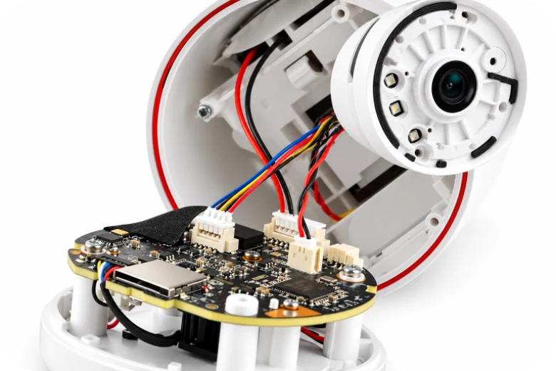

A webcam does not always operate from one main circuit board. A compact USB model may combine the image sensor, video controller and power regulation on a single PCB. A more elaborate camera can distribute those functions across a sensor board, processing mainboard, wireless or Ethernet interface, power board, motor-control board and auxiliary assemblies for audio or illumination. The number of boards follows the camera’s connections, enclosure and functions—not simply its resolution.
Highleap Electronics provides webcam PCB fabrication and PCBA assembly for customer-designed camera electronics, from individual sensor modules to coordinated multi-board sets. Its electronic manufacturing services include approved component sourcing, SMT and through-hole assembly, and agreed inspection or functional testing. The sections below show how different webcam and connected-camera products can divide their electronics, and which details matter when those boards are manufactured together.
Webcam Types and the PCB Assemblies They Use
The word webcam most often refers to a camera connected directly to a computer, typically over USB. Wi-Fi and Ethernet/IP cameras are adjacent connected-camera categories; industrial USB and GigE cameras form another specialized family. Their electronics overlap, but their host interfaces, power arrangements and product tests differ. The following examples describe possible PCB configurations, not fixed requirements for every camera in a category.
| Camera product | Possible PCB / PCBA arrangement |
|---|---|
| USB desktop webcam | One integrated sensor/USB mainboard, or a separate sensor PCB and USB processing board |
| 4K / autofocus webcam | Sensor and processor circuitry, with a lens-actuator interface or separate camera module where used; 4K does not inherently require extra boards |
| Streaming / creator webcam | Video mainboard plus optional microphone, button, indicator or display/control PCBA |
| Conference webcam / video bar | Camera and processing boards, optional microphone-array or audio DSP board, USB/control interfaces and amplifier board where fitted |
| PTZ / auto-tracking camera | Image/video mainboard with optional pan/tilt motor-driver, position-sensor and moving-flex assemblies |
| Wi-Fi smart camera | Image-processing and wireless electronics, power conversion, and optional IR illumination, microphone or battery/charging PCBAs |
| Ethernet / PoE IP camera | Image/video processor board, Ethernet interface, optional PoE power-stage board, IR LED board, I/O or PTZ control board |
| Night-vision / outdoor IP camera | Sensor and processing boards plus optional IR LED driver/illumination, IR-cut filter actuator, surge protection or heater-control PCB |
| Embedded / industrial camera | Sensor PCB and host/interface board, optionally with isolated I/O, trigger, lighting or separate power circuitry; USB3 Vision and GigE Vision differ from ordinary UVC webcams |
A single PCB may combine several of these functions. Conversely, an industrial or motorized camera may use several independently assembled boards for easier mounting, thermal separation or mechanical movement. For broader imaging electronics beyond desktop webcams, camera PCB manufacturing covers related board constructions without assuming a common camera design.
From Image Sensor to Output: What Each Camera Circuit Board Does
In a multi-board camera, the mainboard is only one part of the signal and power chain. A sensor PCB converts light into electrical image data; a controller or ISP/SoC processes that data; an interface circuit delivers it to a host or network. Power and control electronics keep the optical and mechanical subsystems operating at their specified conditions.
Camera sensor board and video-processing mainboard
A webcam image sensor PCB may carry the CMOS sensor, local regulators, clock components and a fine-pitch connector behind the lens. The separate video mainboard may contain the image processor or USB bridge, memory, firmware storage, power sequencing and host interface. Other designs combine both roles on one PCB. Sensor-to-processor routes, including MIPI CSI-2 where specified, must follow the released stack-up and routing requirements rather than generic USB trace rules.
Power, interface and auxiliary PCBAs
A camera power supply PCB or DC/DC board supplies the video processor, sensor, motors and lighting; it may be separate when available space, heat or input voltage warrants it. Interface boards may contain USB connectors, Ethernet magnetics, an approved Wi-Fi module or external I/O. Separate camera control PCBAs can hold the pan/tilt driver, microphone array, IR illumination, indicators or front-panel buttons. None of these needs to be a standalone board unless the released product architecture calls for it.
When boards are separated, connector definitions become part of system manufacturing: mating direction, FPC pin-one location, cable length, rail assignment, board-to-board height and the approved revision of each assembly should be consistent across the full camera set. This is the point at which supplying five individually correct PCBs is not enough if they cannot be paired in the same enclosure.
USB Webcam, Wi-Fi Camera and IP Camera PCB Differences
A conventional USB webcam PCB delivers video to a connected host. Its approved USB controller, firmware and interface determine whether USB Video Class (UVC) is supported, which formats are exposed and how the camera enumerates. USB-C is a connector format; it does not by itself guarantee USB 3.x speed or Power Delivery.
A wireless connected camera adds a Wi-Fi radio or module, antenna and local processing for its particular network/video implementation. The RF keep-out and matching network must be built to the approved design, while the antenna is validated in the actual enclosure. Battery-powered variants may also require charging and protection circuitry; mains-powered smart cameras need not include it.
An IP camera PCB assembly with wired Ethernet instead uses an Ethernet interface and network-capable processing architecture. Where Power over Ethernet (PoE) is specified, the powered-device interface and DC/DC stage must match the approved power standard, isolation and load budget. Those circuits may sit on the mainboard or on a separate PoE power PCB. IP video streaming, ONVIF support and network security depend on the product firmware and intended implementation; they are not implied by fitting an RJ45 connector.
These distinctions affect production testing: a USB camera may require UVC enumeration and video-stream checks; an Ethernet camera may require link negotiation, device identity, network streaming and power-input checks; a Wi-Fi model adds the approved radio connection and configuration. A manufacturer can build the electronics to each specification without treating all connected cameras as a single interface type.
Image Sensor, Lens and Camera FPC Assembly
Optical hardware can make the smallest board the most handling-sensitive PCBA in the product. Image sensor packages and integrated camera modules may have different reflow, cleaning and moisture restrictions. Protective covers, inspection lighting and the point at which the lens is installed should follow the approved supplier instructions.
When a sensor PCB is linked by a flex cable, the connector contact side, latch access, bend path and stiffener thickness must match the assembly drawing. A top-contact FPC socket cannot be substituted for a bottom-contact socket solely because the pitch matches. The relevant camera FPC connection and assembly details become particularly important when the optical head is separate from the USB, Wi-Fi or Ethernet mainboard.
Lens holders, mount holes, cover glass and sensor seating must all reference the correct mechanical datums. Where the order includes optical integration, the OEM’s approved focus procedure, reference target and limits determine acceptance. PCB fabrication and SMT inspection verify the constructed board; optical alignment and image tuning require their own agreed process.
Power Supply, IR LED, PTZ Motor and Audio Control Boards
These are the board types most easily overlooked when a project is described only as a webcam mainboard. They are common in particular feature-rich or network-connected camera designs, but should not be added to products that do not need them.
Separate power and illumination boards where the design requires them
A PoE camera power PCB converts the approved input supply into rails for the processor, sensor and accessories. An externally powered model may instead use a DC-input board, and a battery camera may include charge management. The released power tree determines converter components, isolation boundaries, current capability and thermal design.
Night-vision models may use an infrared LED PCB assembly or an integrated illumination section with controlled LED current, thermal spreading and a sensor for switching illumination modes. Some also incorporate an IR-cut filter actuator, which is a separate mechanical/electrical function from the LED driver. The manufacturing principles behind LED driver PCB assemblies apply when the approved camera includes such lighting hardware.
Motion, microphones and interface controls
A PTZ camera motor control PCB can drive pan, tilt or zoom actuators and receive limit or position signals. Motor-current paths, feedback connectors and moving flexes must follow the released mechanics; their integration differs from the static camera sensor board. The motor driver PCB topic is relevant for the actual motion-control hardware. Other models add microphone or speaker PCBAs, privacy switches, status lights, storage-card interfaces or alarm I/O. The selected BOM determines which subassemblies exist and how they are tested.
Highleap Electronics • PCB Manufacturing & Assembly
One Supplier for Your Camera’s Complete PCB Set
Need a sensor PCB, video mainboard, power board or several assembled camera PCBAs? Send the released files and BOMs for a coordinated quote. Discuss worldwide delivery, after-sales support and payment options for your order.
Worldwide Shipping Options
After-Sales Support
Payment Terms by Agreement
| Get My Quote | Discuss My Build |
Shipping, after-sales coverage and payment terms are confirmed for each order.
Manufacturing and Testing Complete Webcam PCB Sets
Webcam PCB manufacturing and assembly may involve two distinct deliverables: the individual PCBAs and the correctly matched set that fits inside a camera. A sensor board, processor board and power board can each pass electrical inspection but still fail to work together if a cable, connector or firmware variant is mismatched.
A production test follows each board’s actual function
- Sensor / optical board: specified supply rails, sensor identification, image-path response and optical cleanliness or focus check where included.
- USB / video mainboard: programmed firmware, device identity, host enumeration and agreed video-output mode.
- Network board: Ethernet link or approved Wi-Fi connection, identity and specified network/video communication when the fixture permits.
- Power board: output voltages, enable and fault signals, and agreed load behavior; PoE negotiation where part of the design.
- Auxiliary boards: illumination and LED current, motor direction/feedback, microphone channels and control buttons, as applicable.
- Combined assembly: correct board revisions, cable orientation, sensor position and the agreed system-level functional sequence.
Highleap can discuss PCBA functional testing against customer-supplied or jointly agreed fixtures and limits. Firmware tuning, optical calibration, radio performance and network interoperability require specifically defined acceptance procedures rather than a generic claim that every finished camera has been qualified.
Manufacturing release for one board or several
For each board, provide fabrication data (Gerber or ODB++), stack-up and drawings, approved BOM, pick-and-place files, module handling requirements and target quantities. For a multi-board camera, add a board-set list identifying the number of each PCBA per product, matching connector/FPC drawings, approved firmware combinations, power inputs and required tests. This is especially useful for multi-board IP camera PCBA assembly, where optional PoE, IR and PTZ assemblies may create several product variants.
Highleap’s turnkey PCB assembly service can coordinate the approved fabricated boards, purchased electronic components and PCBA operations. Optical modules, wiring, final housing integration and product-level calibration are included when they form part of the agreed order. The result is a quotation built around the camera’s actual electronic assemblies rather than an assumed single mainboard.

Recommended Posts
TMM4 Filter PCB Manufacturing
TMM4 filter PCB manufacturing is controlled by the...
TMM3 PCB Manufacturing for RF Modules
TMM3 PCB manufacturing is most useful where the RF module...
TMM6 PCB Fabrication
TMM6 fabrication is the process-control page for a mid-Dk...
TMM10 PCB Manufacturing for Compact RF Designs
Table of contentsHow TMM10 Shrinks RF StructuresTMM10 vs...
How to get a quote for PCBs
Let’s run DFM/DFA analysis for you and get back to you with a report. You can upload your files securely through our website. We require the following information in order to give you a quote:
-
- Gerber, ODB++, or .pcb, spec.
- BOM list if you require assembly
- Quantity
- Turn time
For PCBA services, please provide your BOM (Bill of Materials) and any specific assembly instructions. We also offer DFM/DFA analysis to optimize your designs for manufacturability and assembly, ensuring a smooth production process.