
EVT, DVT and PVT for PCB Assembly and Product Validation
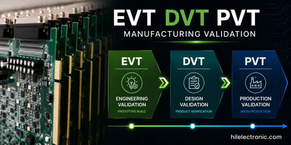
Table of contents
EVT, DVT and PVT — Engineering Validation Test, Design Validation Test, and Production Validation Test — are the three most common stage gates hardware programs use between prototype and mass production. Each stage answers a different question, produces different manufacturing evidence, and requires the PCB assembly line to be run in a different mode. This article covers what each build validates, how the assembly conditions differ, and how Highleap Electronics adapts procurement, SMT, test, and documentation to fit the stage rather than treating every build the same way.
1. EVT, DVT and PVT as Manufacturing Stage Gates
The three stages exist because “prototype to production” is not one step. Each stage narrows a specific class of risk:
- Engineering Validation Test (EVT) confirms that the engineering architecture works. The board powers up, the firmware boots, the key interfaces communicate, and the fundamental design assumptions are correct.
- Design Validation Test (DVT) confirms that the released product design meets its full requirement set — electrical, mechanical, thermal, regulatory, and reliability — under conditions close to volume production.
- Production Validation Test (PVT) confirms that the production system itself — line, procurement, tooling, test, documentation — can deliver that validated design repeatably.
Companies name these stages differently. Some add EP (Engineering Prototype), MP (Mass Production), or intermediate gates. The number of stages, sample counts, and gate reviews depend on the customer’s product development process, not on a universal rule. Highleap runs each stage against the customer’s own definition and does not impose a fixed template.
2. EVT Builds: Proving the Engineering Architecture
EVT is the earliest formal build stage after breadboarding and initial prototypes. The design is still moving. The bill of materials may have placeholder parts. Rework, blue wires, and cut traces on EVT boards are normal — they are how the design team resolves the last architectural questions before committing to a released design.
From a manufacturing perspective, EVT PCB assembly is characterized by:
- High rate of design change. Multiple revisions may be built in quick succession. File control has to accept revision churn while still preventing the wrong revision from reaching the line.
- Acceptable engineering rework. Manual modifications after assembly (jumper wires, resistor stuffing changes, cut-and-strap corrections) are expected and should be captured in a rework record, not hidden.
- Incomplete BOM maturity. Some components may still be generic or preferred rather than final MPN. Highleap flags this rather than silently substituting.
- Limited test scope. Focus is on power-up, boot, and primary interfaces. Full functional testing is usually not defined yet. See prototype PCB handling for the surrounding workflow.
- Small quantities. Enough units to give the design team debug boards and a small margin for damaged units. Volume statistics are not the goal at EVT.
- Process is representative but not final. Standard SMT is used, but stencil design, reflow profile, and fixture design may not be optimized yet.
What EVT can tolerate: temporary alternates for long-lead parts, hand rework, DNP populated in-line with post-build modifications, and simple visual inspection rather than a full inspection stack. What EVT should not defer to DVT: footprint errors that affect placement, obvious DFM violations, and unresolved mechanical interference — because carrying these into DVT costs another build cycle.
Highleap requires the same core file package for EVT as for later stages, but expects and tolerates revision changes. Feedback on file quality, footprint accuracy, and layout risk is returned during EVT so the design team can act before DVT release.
3. DVT Builds: Validating the Released Product Design
DVT is where the design stops being fluid. The PCB structure, BOM, and firmware are close to the final volume version. The mechanical assembly, connectors, and interfaces are as they will ship. DVT builds are usually the first units that can be sent to compliance labs, reliability testing, field trial customers, and regulatory review.
The manufacturing characteristics of DVT include:
- PCB near-production configuration. Same fabricator, stackup, controlled impedance, and surface finish planned for volume — see the underlying PCB manufacturing approach.
- Frozen key components. Critical parts (main processor, power stage, connectors, RF front-end) come from approved sources at their intended MPN.
- Mechanical and interface validation. Boards fit into intended enclosures, mating connectors align, and cable routing has been checked.
- Firmware close to release. Feature-complete firmware runs on DVT units, so functional test and interoperability tests are meaningful.
- Compliance and reliability preparation. Samples are pulled for EMC, safety, environmental, mechanical shock, and thermal cycling — those pulls should be planned into the DVT quantity, not decided afterward.
- Test coverage expanded. AOI and X-ray coverage matches volume intent. Functional test scripts are complete or near-complete. ICT or flying probe strategy is defined.
A practical DVT checklist covers:
- PCB revision at intended volume revision
- BOM at frozen state with approved alternates listed
- Mechanical fit checked in the actual enclosure
- Firmware at the intended DVT release build
- Test fixtures — ICT, FCT, and programming — available or in final build
- Reliability sample count carved out from the DVT run
- Compliance sample count identified and reserved
DVT is the last practical stage to catch a design issue before it becomes expensive. Anything caught in DVT is a design revision; the same issue caught in PVT is a production problem plus a design revision.
4. PVT Builds: Validating the Production System
PVT looks superficially like a small production run, but the intent is different. PVT is not “a bigger DVT.” It is a rehearsal of the volume production system — line, materials, tooling, staffing, documentation, and test — against a design that has already been validated in DVT.
What PVT actually validates:
- The production line configuration. The same SMT line, feeders, reflow oven, and inspection stations that will run volume also run PVT.
- Released work instructions. The written procedures that operators will follow in volume are exercised in PVT — including THT sequences, hand-soldering steps, conformal coating, and packaging.
- Production stencils and fixtures. The final stencil revision, ICT fixture, functional test fixture, and programming rig are in place. Prototype-grade tooling is retired.
- Production sourcing. Parts come from AVL sources under the volume procurement plan, with real MOQ and lead time. Substitutions used earlier are eliminated.
- Production test programs. ICT, FCT, and programming scripts run at final version. Coverage is measured, not assumed.
- Packaging as shipped. Cartons, labels, and shipping-safe packaging are used exactly as they will ship at volume.
- Cycle time and takt. Line rate is measured against the target volume cadence. Bottlenecks are identified before ramp.
- Operator training and instructions. Operators run PVT following volume work instructions. Gaps in training or documentation surface here rather than during ramp.
- Traceability and serialization. Serial numbers are assigned and recorded under the volume traceability system.
- Yield and defect capture. First-pass yield (FPY) is measured. Defect Pareto is generated and closed before volume authorization.
PVT should be run at a quantity that produces meaningful yield data, but the number is not what defines PVT — the production-system validation is. A build of the same size run through a prototype cell with soft-tooling is a large DVT, not a PVT.
5. EVT vs DVT vs PVT: Deliverables and Exit Criteria
A side-by-side view helps clarify what each stage should produce and when the gate is genuinely closed.
| Stage | Main Objective | Typical Build Condition | Required Output | Exit Decision |
|---|---|---|---|---|
| EVT | Prove the engineering architecture | Fluid design, rework accepted, temporary alternates possible | Working debug units, design change list, DFM feedback | Architecture confirmed; move to DVT release |
| DVT | Validate the released design against requirements | Near-production PCB, frozen key parts, feature-complete firmware | Compliance samples, reliability samples, mechanical fit report, expanded test coverage | Design meets specification; ready for production system rehearsal |
| PVT | Validate the production system | Volume line, final tooling, volume sourcing, released work instructions | Yield data, cycle-time record, defect Pareto, traceability records, packaging trial | Production system ready to ramp to mass production |
Where different issues should close:
- Design issues should close at EVT or DVT. Anything design-related surviving into PVT triggers a costly rework loop.
- Manufacturing process issues may appear in DVT but must close by end of PVT.
- Supply chain issues — MPN availability, MOQ, lead time — should be surfaced by DVT and locked before PVT so ramp planning is realistic.
- Test issues — fixture problems, false-call rates, coverage gaps — should be resolved during DVT and confirmed in PVT.
Sample counts are set per project based on statistical need, destructive test consumption, and compliance requirements — Highleap does not publish a fixed number that applies to every product.
6. Plan an EVT, DVT or PVT Build with Highleap
Highleap Electronics runs EVT, DVT, and PVT builds through the same integrated flow used for volume production, adjusting the level of file control, sourcing rigor, and test coverage to match the stage. Because manufacturing services, procurement, assembly, programming, and test sit in one manufacturing route, feedback from one stage carries directly into the next without a supplier hand-off. Highleap is a manufacturing partner in this process, not the compliance or certification authority — regulatory testing is performed by accredited third-party labs on samples produced during DVT and PVT.
To scope a stage build, provide:
- Current stage (EVT, DVT, PVT) and the customer’s own definition of that stage
- Design maturity — whether the schematic and layout are still moving or released
- Current PCB revision and any pending changes
- BOM status — placeholder parts, alternates policy, and frozen items
- Expected build quantity and how validation and destructive samples are counted
- Validation objectives — compliance samples, reliability samples, field trial units
- Test requirements — ICT, flying probe, FCT, programming, boundary scan
- Target volume production date and estimated annual demand
- Whether full turnkey procurement is required or partial consignment applies
- Golden sample or previous-revision sample if available for reference

Recommended Posts

TMM4 Filter PCB Manufacturing
TMM4 filter PCB manufacturing is controlled by the...

TMM3 PCB Manufacturing for RF Modules
TMM3 PCB manufacturing is most useful where the RF module...

TMM6 PCB Fabrication
TMM6 fabrication is the process-control page for a mid-Dk...

TMM10 PCB Manufacturing for Compact RF Designs
Table of contentsHow TMM10 Shrinks RF StructuresTMM10 vs...
How to get a quote for PCBs
Let’s run DFM/DFA analysis for you and get back to you with a report. You can upload your files securely through our website. We require the following information in order to give you a quote:
-
- Gerber, ODB++, or .pcb, spec.
- BOM list if you require assembly
- Quantity
- Turn time
For PCBA services, please provide your BOM (Bill of Materials) and any specific assembly instructions. We also offer DFM/DFA analysis to optimize your designs for manufacturability and assembly, ensuring a smooth production process.