
External SSD Enclosure PCB Manufacturing & Assembly
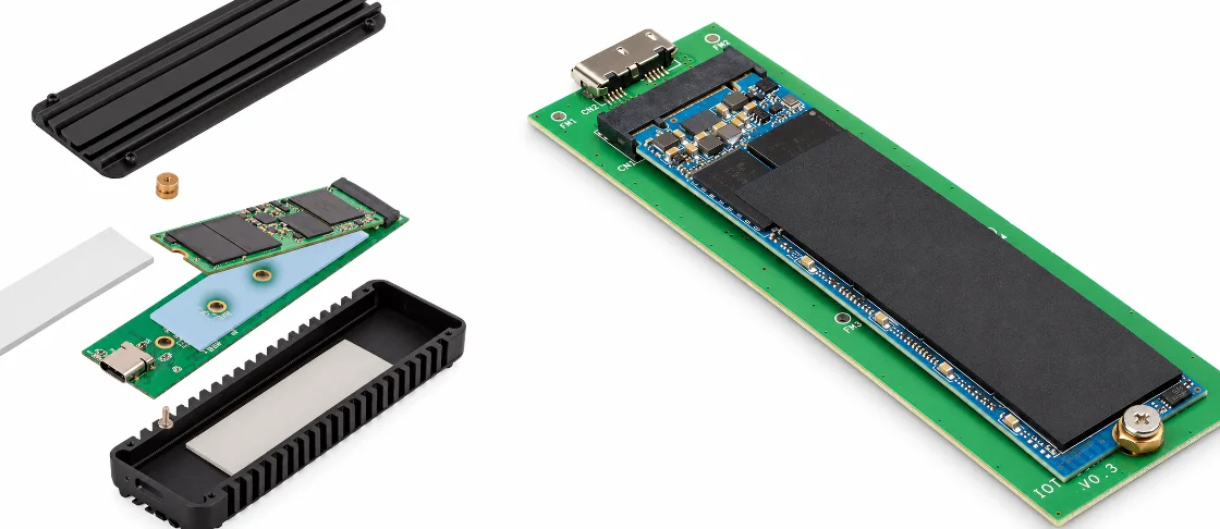

Highleap Electronics manufactures customer-released external SSD enclosure PCBs and PCBAs for USB-to-PCIe bridge designs serving NVMe SSDs, USB-to-SATA designs and generation-specific USB4/Thunderbolt storage architectures. We quote high-speed PCB fabrication, component sourcing, SMT/THT assembly, inspection, programming and customer-defined performance screening, with production review centered on the approved bridge/controller, host and storage-side channels, M.2 mechanics, power integrity and enclosure thermal interface.
Separate External SSD Enclosure Types by Drive Form Factor and Host Interface
Before quoting an external SSD enclosure PCB manufacturer program, the supplier should identify the host-to-storage bridge. For RFQ accuracy, separate three items that are often grouped together: the Type-C receptacle, the host transport implemented by the bridge controller, and the SSD-side interface. An M.2 PCIe/NVMe module and an M.2 SATA module require different bridge architectures and different storage-side routing.
External SSD enclosures are not limited to one NVMe bridge board. The category includes 2.5-inch SATA SSD enclosures, M.2 SATA enclosures, M.2 NVMe USB enclosures, USB4 and Thunderbolt storage products, and multi-drive designs. Each class changes the bridge controller, connector set, power path, enclosure mechanics and sustained-load thermal problem.
SSD Enclosure Product Families Use Different Bridge and Thermal Architectures
- 2.5-inch SATA SSD enclosure: Uses a USB-to-SATA bridge when the host is USB and a 2.5-inch SATA drive on the device side. The board usually has more mechanical room than an M.2 enclosure but must still control SATA connector alignment, drive power and bridge firmware.
- M.2 SATA SSD enclosure: Accepts an M.2 SATA device, which is physically M.2 but electrically different from an NVMe/PCIe SSD. Keying, supported drive type and bridge silicon must be stated clearly so an M.2 socket is not treated as proof of NVMe compatibility.
- M.2 NVMe USB enclosure: Uses a USB-to-PCIe bridge to connect an NVMe SSD. The PCBA must preserve both the host-side USB channel and device-side PCIe channel, while managing bridge and SSD heat inside a compact enclosure.
- USB4 NVMe enclosure: Uses a USB4-based architecture where specified and can place tighter demands on high-speed routing, bridge/router selection and thermal performance than a conventional USB enclosure. The exact USB4 implementation must be released by the OEM.
- Thunderbolt SSD enclosure: A Thunderbolt storage product uses generation-specific Thunderbolt controller/certification requirements rather than being labeled from the USB-C connector alone. Sustained storage transfer makes controller and SSD thermal coupling especially important.
- Dual-drive SSD enclosure: Can support two drives for capacity, independent access or a RAID function depending on the controller architecture. It adds more power, thermal load, connectors and firmware/configuration states.
- External SSD docking station: Uses an exposed/removable drive insertion format instead of a closed enclosure. Socket durability, insertion guidance, ESD and mechanical support become more prominent than in a permanently assembled enclosure.
- Rugged or industrial SSD enclosure: May add locking connectors, wider input-power tolerance, conformal coating or reinforced mechanics if the OEM specifies them. These should be treated as released product requirements rather than generic claims attached to the word “rugged.”
- Actively cooled high-performance enclosure: Adds a fan or other active thermal component where required by the system design. Fan connector, airflow path, firmware/control and acoustic/mechanical constraints then enter the production package.
- Dock or hub with integrated M.2 storage: Combines external storage with docking or hub functions. The board can share Type-C, power and enclosure resources but must separate storage, USB/display and charging test paths by function.
| Product class | Typical architecture emphasis | Manufacturing / test priority |
|---|---|---|
| 2.5″ SATA SSD enclosure | USB-to-SATA bridge | Drive connector/power and mechanical fit |
| M.2 SATA enclosure | USB-to-SATA bridge with M.2 SATA device | Correct keying/drive support and compact thermal path |
| M.2 NVMe enclosure | USB-to-PCIe bridge + NVMe SSD | Two high-speed channel sides and bridge/SSD heat |
| USB4/Thunderbolt storage | Generation-specific high-speed architecture | Tighter SI/material/thermal and compliance boundary |
This broader classification prevents the page from over-optimizing around “NVMe enclosure PCB” alone and captures realistic sourcing terms such as M.2 SATA enclosure PCB, USB4 SSD enclosure PCBA, Thunderbolt SSD enclosure board and dual-drive storage enclosure assembly.
Define the Storage Bridge Topology
| Released topology | What it means | Manufacturing focus |
|---|---|---|
| USB-to-PCIe bridge for NVMe | The USB host path is converted by a bridge controller to PCIe for an NVMe SSD | Two high-speed domains, bridge-controller assembly, M.2 mechanics and thermal load |
| USB to SATA bridge | USB host path is converted to SATA for a SATA SSD/HDD | USB and SATA routing, bridge/power test; do not describe the storage side as NVMe |
| USB4 / Thunderbolt storage design | Uses a generation-specific high-speed controller architecture defined by the OEM | Material/channel controls, controller firmware, compliance boundary and higher thermal density |
| M.2 form factor only | Describes the module connector/mechanics, not the protocol | Confirm whether the installed module is PCIe/NVMe, SATA or another released type |
This architecture determines the controller, reference clocks, power rails, M.2 keying, firmware, test host and expected performance. A sourcing team should therefore include the actual bridge IC and supported SSD type in the RFQ rather than asking the factory to infer capability from the enclosure shape.
Treat the Bridge Controller and M.2 Connector as Product-Defining Parts
- Bridge controller substitutions require engineering approval: Controllers can differ in host capability, PCIe lane support, firmware, thermal behavior, power states and supported SSD types. Component sourcing should use exact or approved parts.
- M.2 keying and module length must match the mechanical release: The connector, standoff position and enclosure should support the intended module. A generic “M.2 socket” is not enough information for assembly.
- USB-C part number must be controlled: The USB-C connector affects board-edge geometry, shell anchoring and cable insertion. It does not define whether the product is USB 3.2, USB4 or Thunderbolt.
- Firmware belongs to the hardware revision: Bridge firmware or configuration EEPROM can affect SSD compatibility, power management and performance. Programming should be versioned with the BOM and test package.
For an OEM external SSD PCBA, topology should also control qualification and production test. NVMe, USB4, Thunderbolt and any transfer-rate class should be assigned only when those functions are explicitly present in the released design and validated with the defined host, bridge, SSD, firmware and cable configuration.
Control Both High-Speed Sides of the Bridge
An NVMe enclosure often contains a host-side high-speed link and a PCIe link to the SSD. The bridge controller joins them logically, but from PCB manufacturing perspective each interface has its own routing and reference requirements. Preserving only one impedance class is not enough.
High-Speed Fabrication Controls
- Map each controlled net class to the actual stack-up: Controlled-impedance requirements should identify host-side and storage-side pairs by layer/reference plane. Trace geometry should be calculated from the approved copper and dielectric build, with any required change reviewed before fabrication.
- Preserve differential breakout and via transitions: Differential routing around the bridge, Type-C receptacle and M.2 connector can be dense. Via anti-pads, reference stitching and layer changes should follow the released layout instead of being normalized by CAM.
- Use a stack-up appropriate to the channel, not the product name: A high-speed PCB stack-up may use conventional multilayer construction or more advanced vias depending on controller pitch, board size and loss budget. “NVMe enclosure” does not automatically mean HDI or one fixed layer count.
- Control laminate substitutions against loss and construction: On higher-speed or longer channels, dielectric loss and copper profile can matter. Tg alone is not a sufficient substitute criterion for a loss-sensitive design.
- Protect the board edge and connector region through panelization: Depaneling stress near USB-C or M.2 connectors can damage joints or alter alignment. Panel tabs and tooling should be planned with the enclosure datum in mind.
A generic high-speed PCB qualification should therefore be followed by a product-specific release review. The factory should know which high-speed channels exist, what the OEM has approved for material/stack-up, and which manufacturing tolerances are critical. It should not promise storage throughput solely from bare-board impedance data.
Do Not Convert Link Rate Into User Transfer Rate
Real external-SSD performance depends on the host controller, USB/USB4 or Thunderbolt implementation, bridge controller, PCIe/NVMe link, SSD media, firmware, thermal throttling, file size and workload. Production screening can compare a unit against customer-defined limits, but a PCB supplier should not publish a fixed MB/s or GB/s claim unless the complete product configuration and test method are controlled.
Manage SSD, Bridge and Power Thermal Paths
External SSD enclosures can be thermally demanding because the SSD controller/NAND and the bridge controller share a small enclosure. High sustained transfer can increase heat in both devices, while power conversion and protection add local losses. Thermal design is therefore tied to component placement, copper spreading and mechanical contact with the enclosure.
Power and Thermal Controls
- Hold the released local power network: A PCB power-integrity review should check regulator loops, decoupling, current paths and connector power pins. Wrong inductor, capacitor or FET substitutions can produce instability or higher losses even when DC voltage looks correct.
- Use thermal vias and copper exactly as released: These structures help move heat into the board or chassis but can also interact with high-speed reference geometry. The manufacturer should not expand copper into a sensitive channel without approval.
- Control heat-spreader and thermal-pad height: If the SSD or bridge contacts the enclosure through a thermal pad, the stack of connector height, standoff, module thickness and pad compression is mechanical production data.
- Keep high-loss components and shields within approved placement: A component alternate with different height or dissipation can break thermal contact or create a hotspot. Mechanical equivalence matters along with electrical equivalence.
- Separate board thermal controls from system qualification: PCB thermal-management features can be reproduced by the factory, but final temperature depends on the installed SSD, enclosure material, airflow, ambient and workload.
For a USB4 SSD enclosure PCB, bridge/controller heat can be significant and may overlap with the SSD hotspot. A pilot build should be evaluated in the intended enclosure under the customer workload, not only as an open PCBA. If the product throttles after several minutes, that is a system behavior that must be correlated with the released thermal design before manufacturing changes are proposed.
Thermal Interface Materials Need Revision Control
Changing thermal pad vendor, thickness, hardness or placement can alter both heat transfer and mechanical force on the SSD module. These materials should be included in the controlled assembly or box-build BOM where Highleap is responsible for installation. A “similar” pad can change SSD bow, connector load or enclosure closure force.
Assemble the Bridge, Type-C and M.2 Interfaces
The bridge controller, USB-C connector and M.2 connector create three different assembly challenges on one small board: fine-pitch or hidden controller joints, mechanically loaded external I/O and a long removable module held by a connector/standoff. The process plan should treat each separately.
Assembly Controls for Bridge, USB-C and M.2
- Bridge-controller packages: Fine-pitch BGA/QFN packages need stencil/reflow control and package-appropriate inspection. Where joints are hidden and risk justifies it, X-ray inspection can support the process acceptance.
- USB-C connector: Verify shell tabs, signal-pin soldering, connector seating and board-edge location. Cable insertion force should be supported by the enclosure/mechanical design, not only fine signal solder joints.
- M.2 connector: Check coplanarity, connector height and alignment to the standoff. The module should insert without forcing or twisting the PCB.
- Standoff/screw hardware: If installed by the PCBA supplier, torque or retention method should be customer-defined. Over-tightening can bow the SSD or PCB and under-tightening can create poor thermal contact.
- Double-sided population: If components sit below the SSD, height and insulation/thermal-pad clearance must be controlled so the module does not contact or crush parts during final assembly.
For an M.2 SSD enclosure PCB manufacturer, first article should include the intended SSD module and housing where possible. Electrical success on a bare fixture does not prove that the installed module clears components, aligns with the standoff or maintains the designed thermal contact.
M.2 defines a family of module/connector form factors and does not by itself identify the storage protocol. Before building the fixture, confirm the exact key, module length, standoff location and whether the released product accepts PCIe/NVMe, SATA or another supported module type.
Distinguish Thermal Throttling From Assembly Instability
During sustained transfer, a reference SSD may intentionally reduce performance as its own controller reaches a thermal-management threshold. That behavior is different from a PCBA that resets, disconnects or corrupts data because of power or signal instability. The OEM test method should therefore define which indicators matter: stable enumeration, error-free read/write, rail behavior and perhaps a minimum sustained rate under a specified reference configuration. A falling benchmark number alone does not identify the failure mechanism.
For NPI, record the installed SSD model, firmware, enclosure, thermal pad, ambient condition and workload. Those details make thermal results comparable. Without them, two identical PCBAs can appear to have different “SSD performance” simply because the SSD controller, host or heat-transfer condition changed.
Screen Function, Performance and Thermal Stability
A storage enclosure needs more than enumeration testing. Production test should detect wrong bridge firmware, unstable power, connector defects and gross performance failures, while product qualification handles wider host/SSD compatibility and long-duration reliability.
Layered Production Test
- Configuration check: Verify PCB/BOM revision, bridge firmware/configuration, M.2 connector/standoff and product label.
- Power-up: Check critical rails and current/fault behavior against customer limits before installing an expensive SSD if the procedure allows.
- SSD detection and enumeration: Install the approved reference SSD and confirm the host detects the enclosure and storage device correctly.
- Read/write/verify: Run the customer-defined data pattern and duration. The criterion should be repeatable and sized for manufacturing screening rather than an undefined “speed test.”
- Sustained-transfer check where required: For products sensitive to thermal throttling, use a customer-defined workload long enough to detect gross thermal/power instability. Record enclosure/ambient conditions if temperature is part of the limit.
- Mechanical fit: Confirm connector alignment, SSD installation, screw/standoff and thermal-interface contact on pilot units.
Highleap can execute customer-defined functional testing when the host, SSD, cable, utility, firmware and pass/fail criteria are defined. A production transfer-rate threshold should be tied to a reference SSD and host because changing either can move the result even when the PCBA is identical.
Keep Compatibility Qualification Outside the Line Test
The OEM may need to qualify multiple SSD brands, capacities, NAND/controller combinations, operating systems and host platforms. That matrix is broader than a factory test. Production should use a controlled reference set that detects assembly drift; product engineering should own the wider compatibility list and update manufacturing only when a validated change is released.
Use NPI Failures to Separate Signal, Power and Thermal Problems
| Observed symptom | First production checks |
|---|---|
| Enclosure does not enumerate | Bridge firmware, host connector, power rails, reference SSD and high-speed path assembly |
| Connects but resets during write | Power integrity, regulator heating, connector resistance and bridge/SSD workload |
| Performance is low but stable | Host/cable capability, bridge mode, SSD link, thermal throttling and reference configuration |
| Works open-board but fails in housing | Thermal interface, connector stress, module/standoff alignment and enclosure grounding/contact |
This diagnostic split keeps the factory from “fixing performance” by changing PCB geometry before basic power, firmware and thermal conditions are verified. High-speed storage failures are often system interactions, so the production investigation should start from controlled reference hardware.
Source the Enclosure as a Controlled High-Speed PCBA
For an external SSD enclosure PCB manufacturer, an accurate quote should reflect the real high-speed and thermal architecture. The RFQ must show whether the product uses a USB-to-PCIe bridge for NVMe, a USB-to-SATA bridge, a generation-specific USB4/Thunderbolt design or another released architecture, because that choice changes material, controller cost, assembly risk, firmware and testing.
RFQ Package
- PCB fabrication: Gerber/ODB++, fab drawing, stack-up, controlled net classes, material requirements and special via details.
- Assembly: BOM, centroid, assembly drawings, USB-C and M.2 connector drawings, approved alternates and thermal hardware.
- Storage definition: Supported M.2 key/module length, PCIe/NVMe or SATA requirement, reference SSD list and any prohibited modules.
- Programming: Bridge firmware/configuration, serial or identity data and version rules.
- Test: Host, cable, reference SSD, read/write utility, load duration, performance limits and thermal/mechanical checks.
Related PCB/PCBA Programs
Can Highleap substitute an M.2 connector or bridge IC?
Only through the customer’s approved alternate or engineering-change process. Connector height/keying and bridge controller firmware, protocol support, thermal behavior and layout requirements can all change. These are product-defining parts, not generic commodity substitutes.
What should be frozen after pilot approval?
Freeze the PCB stack-up/material, approved BOM, bridge firmware, USB-C/M.2 mechanical criteria, thermal-interface materials, assembly traveler, reference SSD/host setup and production test limits. That package is what allows repeat lots to match the accepted enclosure behavior.
How should SSD compatibility changes enter production?
A new reference SSD should be validated with the released bridge firmware, power design, M.2 mechanics and thermal stack before it replaces the previous production media. Capacity or brand alone is not a sufficient equivalence rule; SSD controller behavior, power states and thermal characteristics can change the result of the same enclosure test.

Recommended Posts

TMM4 Filter PCB Manufacturing
TMM4 filter PCB manufacturing is controlled by the...

TMM3 PCB Manufacturing for RF Modules
TMM3 PCB manufacturing is most useful where the RF module...

TMM6 PCB Fabrication
TMM6 fabrication is the process-control page for a mid-Dk...

TMM10 PCB Manufacturing for Compact RF Designs
Table of contentsHow TMM10 Shrinks RF StructuresTMM10 vs...
How to get a quote for PCBs
Let’s run DFM/DFA analysis for you and get back to you with a report. You can upload your files securely through our website. We require the following information in order to give you a quote:
-
- Gerber, ODB++, or .pcb, spec.
- BOM list if you require assembly
- Quantity
- Turn time
For PCBA services, please provide your BOM (Bill of Materials) and any specific assembly instructions. We also offer DFM/DFA analysis to optimize your designs for manufacturability and assembly, ensuring a smooth production process.