
Gaming Steering Wheel PCB Manufacturing & Assembly for Button, Paddle, Encoder and Display Wheel-Rim Modules
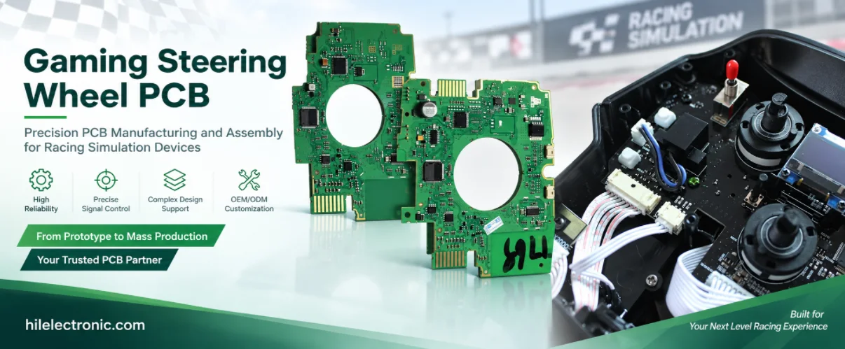

The electronics inside a detachable gaming steering wheel are very different from the motor controller inside the wheel base. A wheel-rim PCB primarily handles player controls: shift paddles, rotary encoders, pushbuttons, clutch paddles, LEDs, displays and the electrical interface through a quick-release or hub. Highleap Electronics manufactures customer-released gaming steering wheel PCB and PCBA assemblies for sim-racing wheel rims, formula-style control wheels, GT-style button plates and modular steering-wheel electronics, while force-feedback motor power remains a separate wheel-base function unless the released design combines them.
Define the Boundary Between Wheel-Rim PCB and Wheel-Base Controller
Separating these two assemblies prevents confusion during manufacturing, sourcing and product definition. The racing wheel controller PCB in the base deals with motor drive, position feedback and high current. The gaming steering wheel PCB in the rim deals with user input, display/lighting and the rotating electrical connection. The two may communicate through slip rings, spring contacts, a cable, a contactless link or another OEM-defined interface.
| Wheel-rim subsystem | Typical electronics concern | Mechanical concern |
|---|---|---|
| Shift paddles | Switch/Hall input and debounce | Paddle travel, magnet/switch alignment and return force |
| Rotary encoders | A/B sequence, push switch and scanning | Detent feel, knob clearance and shaft support |
| Clutch paddles | Analog Hall/potentiometer channels | Dual-paddle range, center or bite-point mechanics |
| LED indicators | Driver current, serial chain and power noise | Light-pipe alignment and diffuser stack |
| LCD/OLED display | FPC, power, data and firmware | Window alignment, protective lens and cable routing |
| Quick-release interface | Power/data/ground and ESD | Contact compression, concentricity and repeated mating |
Paddles, Buttons and Rotary Encoders Need Physical-Position Testing
A wheel can contain controls on the front plate, rear paddles and side grips. The same switch part may appear many times, making a mapping error easy to miss. Final test should identify controls by physical label or position rather than by connector number alone.
- Shift paddles: verify left/right mapping, actuation point and repeated return after enclosure assembly.
- Dual-clutch paddles: if analog, capture both raw ranges and customer-defined combined behavior; if digital, test each state separately.
- Rotary encoders: rotate several detents in both directions and verify no missed or reversed counts.
- Momentary buttons: test through the actual cap, membrane or front-panel stack so switch height is validated.
- Toggle/multi-position switches: verify every stable position and any guarded or pull-to-turn mechanism that exists in the product.
Mechanical tolerances can look like switch faults
A front plate that sits too close to an encoder knob may create side load. A paddle magnet mounted too far from a Hall sensor can reduce margin. A light pipe can press against a PCB-mounted button. The PCBA should therefore be checked in the completed wheel shell before manufacturing acceptance is finalized.
LED Arrays and Steering Wheel Displays Add Power and Assembly Density
Formula-style and GT-style gaming steering wheel PCBs may include shift-light LEDs, flag indicators, seven-segment displays, OLEDs or LCD modules. These features create a denser board than a simple gamepad and can require careful FPC handling, LED orientation, thermal review and current budgeting.
Display path
Module revision, FPC seating, power sequencing and customer test image.
LED path
Driver, polarity, chain order, current setting and light-pipe alignment.
Input path
Ensure lighting activity does not disturb analog paddles, encoders or data communication.
If the display sits on a daughterboard, Highleap can coordinate controller and display PCB assembly with the released FPC or board-to-board connector. Cosmetic handling matters because a scratched display window or contaminated lens can force rework after the electronics have already passed.
Quick-Release Contacts, Slip Rings and Hub Interfaces
A detachable wheel needs an electrical connection that survives rotation or repeated removal. The exact implementation is product-specific, but all versions require clear production limits for contact alignment, power-up sequence and communication stability.
- Spring/pogo contacts: verify contact height, PCB flatness, mating compression and contamination control.
- Circular or keyed connector: inspect solder anchors, shell grounding and mechanical key alignment.
- Slip ring: test data/power continuity through rotation using the released wheel-base assembly or validated fixture.
- Board-to-board quick release: ensure pins cannot be partially mated or shifted by hub tolerance.
- Wireless rim if present: radio, battery and charging functions should follow the released wireless and RF architecture rather than being assumed from the product type.
Steering-wheel brands may use mechanically similar hub interfaces with different power, pinouts or protocols. Manufacturing should validate the exact wheel base or customer fixture specified in the project. Highleap should not generalize compatibility from connector appearance.
Wheel-Rim Firmware, Device Identity and Variant Control
One wheel-rim PCB can support several faceplate or display versions. The hardware population, LED map, display firmware and button labels must remain aligned. If the rim contains a local MCU, its firmware revision should be recorded with the assembly. If the wheel base provides all processing, then the rim’s resistor coding, EEPROM or identity method should be built and tested exactly as released.
A configuration matrix is especially useful when the same PCB ships with different encoder counts, clutch paddles, screen modules or logos. Production should identify the functional differences, not only cosmetic SKU names.
Highleap Electronics • PCB Manufacturing & PCBA
Send the released PCB files, BOM, assembly data, mechanical constraints, firmware or programming package, test requirements and target quantities for a manufacturing review.
Request a Steering Wheel PCB Quote →Discuss Your PCBA Build →
✓ DFM and DFA review✓ Prototype to repeat production✓ PCB fabrication and assembly
Gaming Steering Wheel PCB Manufacturing for US, European and Asian Brands
A sim-racing brand in the United States, Canada, Germany, the United Kingdom or Italy may source gaming steering wheel PCB assembly from China while machining the wheel plate and quick-release hardware locally. Teams in Japan or South Korea may use locally selected encoders, switches or displays while Highleap builds the customer-released PCBA. In all cases, sending the actual faceplate, paddle mechanism and hub connection makes the NPI review more valuable than sending Gerber files alone.
For international repeat production, Highleap can keep the approved BOM, PCB revision, programming image and final test tied to each wheel-rim variant. The OEM remains responsible for wheel-base compatibility and system-level product validation.
End-of-Line Test and RFQ Inputs for Gaming Steering Wheel PCBA
- Programming/power: verify local MCU or rim identity and current consumption.
- Input map: test every button, paddle, toggle and encoder by physical position.
- Analog paddles: sweep clutch or other analog controls and confirm raw/calibrated range.
- LED/display: run the customer pattern and inspect sequence, pixels/segments and light-pipe alignment.
- Hub connection: connect through the released quick release and confirm stable power/data while rotating or handling as specified.
- Final enclosure: repeat critical controls after faceplate, grips and rear housing are tightened.
For quotation, send PCB fabrication data, BOM, assembly drawings, faceplate/housing files, paddle and encoder specifications, display module information, quick-release connector data, firmware and customer functional test. Highleap can support DFM, PCBA, component sourcing and final functional verification around the released wheel-rim design.
Dense Wheel-Rim PCB Layouts Need Careful Assembly and Inspection
Formula-style steering wheels can place many encoders, LED drivers, display connectors and MCU components on a board that follows the shape of the rim. Edge cutouts, mounting holes and closely spaced controls reduce routing freedom. The design may use fine-pitch devices or small connectors even if it does not require the HDI density of a handheld console. Assembly review should focus on stencil access, connector coplanarity, board support and component clearance to the faceplate.
- Encoder alignment: shafts should remain perpendicular to the front panel after soldering.
- Large switch hardware: through-hole joints need sufficient solder while keeping flux away from mechanical contacts.
- Display FPC: connector latches should be accessible and protected during final wheel assembly.
- LED orientation: sequence and color variants should be checked against the released placement map.
- Curved/irregular board outlines: depanelization and handling fixtures should avoid bending narrow sections around controls.
Quick-Release Durability Should Include Contact Resistance and Communication Margin
Repeated wheel removal can polish, contaminate or mechanically wear the hub contacts. The PCBA factory does not need to run the full lifecycle test on every unit, but NPI and qualification can define a representative mating sample. After the prescribed cycles, the wheel should still power correctly and maintain stable data through rotation or normal handling.
If the electrical interface shares power and high-speed or serial data through a compact contact set, contact resistance changes can appear as display resets or LED flicker before the wheel loses all communication. The customer test should therefore monitor more than “device connected.” It can exercise all LEDs, display traffic and inputs together while the wheel is attached through the production quick release.
Wheel-Rim Power Budget and Grounding Matter Even Without a Force-Feedback Motor
The steering wheel PCB may be low power compared with the wheel base, but bright LED arrays and displays can create substantial transient load over a small contact interface. If the hub supplies the rim, voltage drop across contacts and cable paths should be tested under the highest released lighting condition. Analog clutch paddles or Hall sensors should remain stable while the display and LEDs update.
Metal faceplates, carbon-fiber structures, aluminum hubs and external paddle hardware can also change the ESD and ground path. Final assembly should preserve the approved shell/chassis bonding and external-port protection rather than assuming the wheel base alone handles all discharge events.
Wheel-Rim DFT, Programming and Service Rework
Useful DFT points include main input rail, MCU rail, reset, programming interface, display power and quick-release data lines. Diagnostic firmware can expose raw button/encoder/paddle states and the installed display or rim identity. Those features make it easier to separate a PCBA fault from a faceplate, paddle or hub problem.
Rework rules should specify what must be retested. Replacing a display requires display and lighting verification; replacing an encoder requires direction/count testing; replacing a quick-release connector requires full hub power/data testing; reprogramming the MCU requires the complete control map. This protects repeat-production quality without forcing unnecessary full teardown for cosmetic repairs.

Recommended Posts
TMM13i PCB Manufacturing
TMM13i PCB manufacturing is aimed at ultra-compact RF...
TMM Temperature Stable PCB Manufacturing
Table of Contents Rogers TMM Temperature Stable PCB...

TMM PCB for Antenna Miniaturization
The antenna-miniaturization page is intentionally narrower...
TMM10 PCB Fabrication
TMM10 fabrication is the process-specific page for a...
How to get a quote for PCBs
Let’s run DFM/DFA analysis for you and get back to you with a report. You can upload your files securely through our website. We require the following information in order to give you a quote:
-
- Gerber, ODB++, or .pcb, spec.
- BOM list if you require assembly
- Quantity
- Turn time
For PCBA services, please provide your BOM (Bill of Materials) and any specific assembly instructions. We also offer DFM/DFA analysis to optimize your designs for manufacturability and assembly, ensuring a smooth production process.