
Hall Effect Keyboard PCB Manufacturing & PCBA
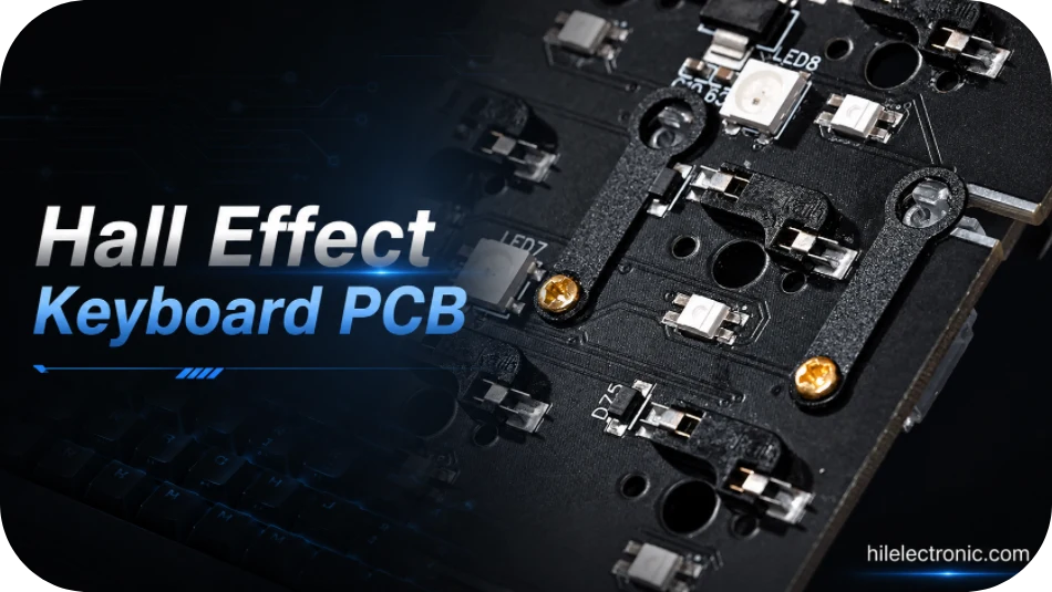
Hall Effect keyboards replace ordinary contact-only key detection with magnetic position sensing, allowing analog input, adjustable actuation and rapid-trigger functions. Highleap Electronics provides PCB fabrication and turnkey PCB assembly for a wide range of electronic products, with magnetic keyboard electronics forming one specialized project category. The manufacturing scope can include bare PCBs, per-key Hall sensors, analog multiplexers or ADC circuitry, MCU and USB interfaces, RGB, optional wireless functions, firmware programming, calibration, traceable testing and enclosure integration.
Consistent performance depends on the complete electromechanical stack: magnetic switch, magnet polarity and strength, sensor package, sensor-to-magnet distance, plate, PCB thickness and flatness, enclosure and firmware calibration. Highleap reviews these items together before quotation and controls sensor placement, soldering, board revision, programmed firmware and end-of-line results so electrically functional PCBAs also meet the approved actuation and repeatability limits after final assembly.
Hall Effect Keyboard PCB Buying Specifications
Highleap can quote a magnetic keyboard PCB as a bare board, a populated hall sensor keyboard PCB, or a complete analog keyboard PCB assembly with firmware and calibration. Custom Hall Effect keypad PCB projects, rapid-trigger products and magnetic-switch controller boards are reviewed against the same controlled production package rather than treated as ordinary switch-matrix assemblies.
| Procurement item | Highleap supply and quotation basis |
|---|---|
| Supply format | Bare PCB, partially assembled board, turnkey Hall Effect keyboard PCBA, programmed module or box-build scope. |
| Sensor architecture | Per-key linear Hall sensors, grouped analog channels or customer-defined magnetic sensing architecture. |
| PCB and interface options | Rigid PCB, multilayer routing, USB-C, RGB, displays, encoders and optional wireless hardware after DFM review. |
| Assembly scope | Sensor array, MCU, analog front end, connectors, LEDs, switches or sockets and secondary mechanical parts as specified. |
| Production test | Programming, USB enumeration, sensor response, noise baseline, key travel, calibration, RGB and customer-defined rapid-trigger checks. |
| Prototype MOQ | Hall-sensor prototypes can enter Highleap’s published low-MOQ assembly program from 5 PCBAs. Sensor reels, custom magnetic switches, long-format panels and calibration fixtures may make a larger engineering lot more economical. |
| Lead-time commitment | The Hall Effect schedule is committed after sensor/MCU stock, PCB geometry, switch samples, firmware and calibration-fixture readiness are checked. Highleap’s assembly lead-time guidance is used as a planning reference, while the quotation states the actual project milestones. |
| Primary cost drivers | Sensor count, sensor package, MCU/ADC architecture, board length, layer count, calibration fixture, switch samples, test time and component availability. |
| Preferred quotation files | Submit Gerber X2/RS-274X or ODB++, Excellon drills, BOM, centroid, assembly and fabrication drawings, plus Hall sensor data, switch/magnet drawings, firmware and calibration limits. The base formatting rules are listed in Highleap’s PCBA file checklist. |
| Important limitation | Highleap does not define actuation curves or approve a magnetic switch substitution without customer-controlled performance limits and mechanical data. |
The Highleap rigid-PCB table lists factory limits such as 60 layers, 2/2 mil trace/space and 0.2–8.0 mm thickness. A Hall Effect keyboard is released to a narrower project window based on sensor pitch, board length, copper balance, flatness and calibration-fixture access; unrelated maximum values are not combined automatically.
Hall Sensor and Analog Keyboard PCB Architectures
Highleap supports build-to-print magnetic keyboard electronics using per-key Hall sensors or grouped sensor channels, depending on the customer architecture. Linear Hall devices convert magnetic-field changes into an analog signal, which allows the controller to estimate key position rather than only detect an on/off threshold. That behavior is the basis for adjustable actuation, analog input and dynamic reset features. The sensor orientation and magnetic field direction must match the selected package; the general sensing principles are described in the Texas Instruments Hall-effect sensor guide.
Highleap also supports custom Hall Effect keyboard PCB and magnetic switch PCB assembly projects where the customer needs a single supplier for PCB, PCBA, firmware programming and calibration. For an OEM magnetic keyboard PCB, the drawing must identify the released switch family, sensor orientation, plate datum and approved calibration method.
Projects that are still selecting the switch ecosystem can use Highleap’s magnetic switch keyboard PCB production review to freeze the magnet, sensor and mechanical interfaces before tooling.
| PCB subsystem | Manufacturing requirement | Highleap review |
|---|---|---|
| Hall sensor array | Consistent footprint, rotation, height and solder volume across every key | Check land pattern, stencil aperture, package orientation, fiducials and AOI visibility. |
| Analog front end | Stable supply, reference, filtering and channel routing | Review decoupling, grounding, mux/ADC routing and separation from LED switching noise. |
| Keyboard controller | Enough ADC, timing and memory resources for the specified firmware | Confirm MCU/package, programming interface, oscillator, boot control and test access. |
| USB and power | Protected USB-C or cable input with stable rail behavior | Review ESD, current budget, regulator loading and connector reinforcement. |
| Lighting and accessories | RGB, display, encoder or wireless features without corrupting sensor readings | Separate noisy power paths and define performance modes for validation. |
Typical products include competitive gaming keyboards, analog-control keypads, magnetic-switch macropads, training consoles and custom input devices. Highleap can manufacture the bare PCB only, or deliver a programmed PCBA ready for mechanical integration.
Hall Effect Keyboard PCB Manufacturing Capabilities
The following values are taken from the published Highleap rigid PCB capability table. They are factory-level limits, not a promise that every extreme can be combined in one build. For Hall Effect boards, the practical route is driven by sensor pitch, board length, layer count, flatness, USB/RF requirements and the calibration fixture.
| Manufacturing item | Published Highleap capability | Project condition |
|---|---|---|
| Maximum layer count | Up to 60 layers | Actual stackup is released after DFM review. |
| Minimum inner/outer trace and space | 2/2 mil | Copper weight, board size and process combination can change the practical limit. |
| Finished board thickness | 0.2–8.0 mm | Keyboard mechanical stack and connector height usually control the selected thickness. |
| Finished board size | 10 × 10 mm minimum; 22.5 × 47.5 in maximum | Panel utilisation, outline shape and assembly support must be reviewed. |
| Outline tolerance | ±0.1 mm | Critical switch, plate and enclosure interfaces should be dimensioned on the drawing. |
| Minimum SMT pad capability | 7 × 10 mil | Component package and paste aperture remain subject to assembly review. |
| Minimum BGA pitch | 7 mil | Final package assembly depends on pad design, stencil, via strategy and inspection plan. |
| Published surface finishes | ENIG, ENEPIG, OSP, HASL, immersion silver/tin, hard gold and others | Finish is selected for solderability, contacts, cost and storage requirements. |
| Bow and twist | 0.3% | Thin or long keyboard boards require panel and fixture review to maintain flatness. |
A conventional full matrix may be replaced or supplemented by analog sensor channels, so routing density can increase quickly. Highleap uses PCB DFM checks to review pin escape, ground return, LED current paths, sensor keepouts, programming pads and panel support before tooling.
Sensor Alignment, Board Tolerance and Magnetic Switch Fit
Magnetic sensing accuracy depends on the relative position of the magnet and sensor. PCB fabrication alone cannot compensate for an uncontrolled switch stem, plate opening, sensor height or enclosure stack. Highleap therefore requests the switch drawing, magnet polarity, travel range, plate data and mechanical datum scheme before the first article.
When the product also requires movement-based reset behavior, the acceptance plan should align with the dedicated rapid trigger keyboard PCB manufacturing process.
- Footprint control: the Hall sensor center, rotation and package datum are checked against the magnet path.
- Board flatness: panel design, copper balance and reflow support are reviewed because local warpage changes the magnet-to-sensor distance.
- Assembly height: paste volume and package seating are controlled to avoid key-to-key sensitivity variation.
- Mechanical datums: tooling holes, plate screws, stabilizers and enclosure references are dimensioned from a common coordinate system.
- Magnetic environment: speakers, steel plates, magnets and other nearby parts are considered during product-level validation.
Highleap can provide dimensional reports or first-article measurements for customer-defined critical features. The drawing should identify the tolerances that affect calibration instead of applying unnecessarily tight limits to the whole board.
Rapid Trigger Calibration, Firmware and Adjustable Actuation
Highleap does not treat firmware as an afterthought. A production Hall Effect PCBA normally requires channel discovery, raw-value capture, baseline storage, travel mapping, dead-zone handling and pass/fail limits. Rapid Trigger behavior also depends on stable position data; it cannot be validated from a solder-joint inspection alone. Wooting describes Rapid Trigger as changing actuation and reset behavior dynamically with key movement, which illustrates why the PCB, sensor readings and firmware must be tested together: official Rapid Trigger product explanation.
| Production stage | Recommended output | Purpose |
|---|---|---|
| Engineering sample | Raw sensor map, noise observation and mechanical fit report | Confirm architecture before production tooling. |
| Golden unit | Approved calibration limits and expected key-travel response | Provide a reference for fixture correlation. |
| First article | Per-key calibration data, firmware version and functional result | Release the assembly process. |
| Volume production | Automated pass/fail record with serial or lot traceability | Control drift and identify affected units. |
| After-sales analysis | Stored test data and revision history | Separate design, component, assembly and mechanical causes. |
Programming can be performed through SWD, USB bootloader, UART or another customer-defined interface. Highleap can integrate IC programming with assembly and maintain the approved firmware checksum by revision.
Hall Effect Keyboard PCBA Assembly and Inspection
The assembly route is planned around many identical small sensors, LEDs and diodes distributed across a long board. Highleap uses stencil segmentation, board support and inspection programming suited to repetitive arrays. The exact process is confirmed through the Highleap SMT capability review.
The end-of-line coverage can be built around Highleap’s keyboard PCBA testing service and broader PCB assembly controls.
- incoming verification of Hall sensors, MCU, regulators, connectors and switch-related components;
- solder-paste inspection where required, followed by controlled reflow and board support;
- AOI for polarity, rotation, presence and solder-joint coverage;
- X-ray inspection when hidden pads, QFN thermal pads or BGA packages are used;
- firmware loading, USB enumeration, current measurement and key-channel communication checks;
- customer-defined calibration, RGB, encoder, display and switch-motion testing.
For magnetic hot-swap products, the switch socket or mechanical retention system must be reviewed as part of the same assembly. Highleap does not assume compatibility between magnetic switch brands merely because the outside shape appears similar.
Representative Hall Effect Production Configurations
The configurations below illustrate how a Hall Effect project can be divided into a controlled manufacturing and test scope. Final architecture and acceptance limits remain customer-defined.
| Representative configuration | Typical hardware scope | Production and acceptance focus |
|---|---|---|
| Competitive analog input board | Per-key Hall sensors, USB-C, RGB and adjustable actuation firmware | Sensor height control, noise measurement, calibration and latency-oriented functional test. |
| Magnetic control keypad | Compact custom Hall Effect keypad PCB with industrial connector and sealed enclosure interface | Mechanical datum inspection, channel calibration and complete input report. |
| Wireless Hall controller | Hall sensor array, BLE SoC, battery charging and low-power modes | Antenna keepout, current testing, sensor calibration and pairing verification. |
Prototype MOQ, Lead Time, Quality Records and Support
Highleap offers prototype, NPI and scheduled production routes. A committed delivery date is issued after the files, sensor supply, magnetic-switch interface, firmware and test method are reviewed. The schedule separates PCB fabrication, component sourcing, assembly, fixture preparation, calibration and final inspection, allowing the buyer to see which item controls shipment.
For long-lead sensors, MCUs and connectors, Highleap can combine production planning with electronic component sourcing and approved-alternate control.
| Control point | Buyer receives | Risk reduced |
|---|---|---|
| Engineering release | Written DFM questions and approved production assumptions | Prevents sensor or switch mismatch from reaching assembly. |
| Material and component readiness | Confirmed PCB material, sensor, MCU and connector status | Avoids unsupported delivery promises. |
| First-article approval | Measured build and agreed test evidence | Stops volume production before system behavior is proven. |
| Lot shipment | Electrical, inspection and functional records as specified | Supports incoming inspection and traceability. |
| After-sales response | Containment, record review, failure-analysis coordination and corrective action | Provides one route for PCB, assembly and test issues. |
The quality package can include bare-board electrical test, dimensional data, AOI/X-ray records, firmware version, calibration logs and customer-defined functional results. Requirements should be stated in the RFQ so they are priced and recorded from the first build.
Why Highleap Reduces Hall-Effect Production Risk
- PCB fabrication, Hall sensor SMT assembly, firmware loading and calibration can be managed under one revision-controlled order.
- DFM covers both electrical data and switch/plate/enclosure datums before tooling.
- Prototype fixtures can be expanded into repeatable NPI and volume test stations.
- Component sourcing, consignment and approved alternates can be separated for risk control.
- Failure analysis can use PCB, BOM, firmware and calibration records from the shipped lot.
Hall Effect Keyboard PCB Manufacturing FAQ
The following long-tail questions explain Hall sensor keyboard design, magnetic switch compatibility, calibration, rapid-trigger capability and production requirements.
How does a Hall Effect keyboard PCB detect key movement?
A magnet moves with each key while a Hall sensor measures the changing magnetic field. The MCU samples that signal and firmware converts it into key position, actuation and release events. This allows adjustable actuation and analog behavior that are not available from a simple open-or-closed mechanical contact.
What is the difference between a Hall Effect keyboard and a mechanical keyboard PCB?
A mechanical keyboard PCB mainly scans switch contacts through a digital matrix. A Hall Effect PCB needs analog sensors, stable references, ADC or multiplexer resources, signal filtering and calibration data. It is also more sensitive to switch geometry, PCB flatness, plate position and magnetic tolerances.
Why is sensor-to-magnet distance important in Hall Effect keyboard design?
The distance determines the usable signal range and whether the sensor remains within its linear measurement window throughout key travel. Variations caused by plate thickness, switch housing, solder height or PCB warp can change actuation behavior, so the mechanical drawings and tolerance stack should be reviewed with the sensor data.
Can one Hall Effect keyboard PCB work with different magnetic switch brands?
Not automatically. Switches may use different magnet strength, polarity, travel, center position and housing geometry. A different switch can require new mechanical verification, sensor selection, calibration curves and firmware limits even when it fits the same plate opening.
How is every Hall Effect key calibrated during PCBA production?
A fixture can move or press each key through defined positions while recording baseline and travel values. Calibration constants may be stored in the device or associated with its serial number. The customer should approve the travel points, pass/fail limits, retest method and the reference mechanical assembly.
Can a Hall Effect keyboard PCB support rapid trigger and adjustable actuation?
Yes, when the analog signal range, sampling architecture and firmware algorithm support those features. The PCB and PCBA manufacturer can build and test the approved design, while the customer normally owns the trigger algorithm, user settings and advertised performance claims.
What files are required for a Hall Effect keyboard PCB quote?
Provide fabrication and assembly data, schematic, BOM, Hall sensor part number, switch and magnet drawings or samples, plate and enclosure files, firmware, programming method, calibration limits, functional test procedure, quantities and delivery requirements.
What causes noise or inconsistent readings on a Hall sensor keyboard PCB?
Common causes include unstable analog supplies, poor grounding, RGB or switching noise, unsuitable ADC range, sensor placement variation, magnetic interference, PCB flex and inconsistent mechanical travel. Layout review and testing should evaluate the complete operating condition rather than only a static sensor value.
Can a complete Hall Effect keyboard PCBA and enclosure assembly be supplied?
Yes. Highleap can quote PCB fabrication, PCBA, programming, per-key calibration, functional testing, mechanical integration, labels and final packing when the approved switches, enclosure parts, firmware and acceptance criteria are available.

Recommended Posts

TMM4 Filter PCB Manufacturing
TMM4 filter PCB manufacturing is controlled by the...

TMM3 PCB Manufacturing for RF Modules
TMM3 PCB manufacturing is most useful where the RF module...

TMM6 PCB Fabrication
TMM6 fabrication is the process-control page for a mid-Dk...

TMM10 PCB Manufacturing for Compact RF Designs
Table of contentsHow TMM10 Shrinks RF StructuresTMM10 vs...
How to get a quote for PCBs
Let’s run DFM/DFA analysis for you and get back to you with a report. You can upload your files securely through our website. We require the following information in order to give you a quote:
-
- Gerber, ODB++, or .pcb, spec.
- BOM list if you require assembly
- Quantity
- Turn time
For PCBA services, please provide your BOM (Bill of Materials) and any specific assembly instructions. We also offer DFM/DFA analysis to optimize your designs for manufacturability and assembly, ensuring a smooth production process.