
Rapid Trigger Keyboard PCB Manufacturing & PCBA
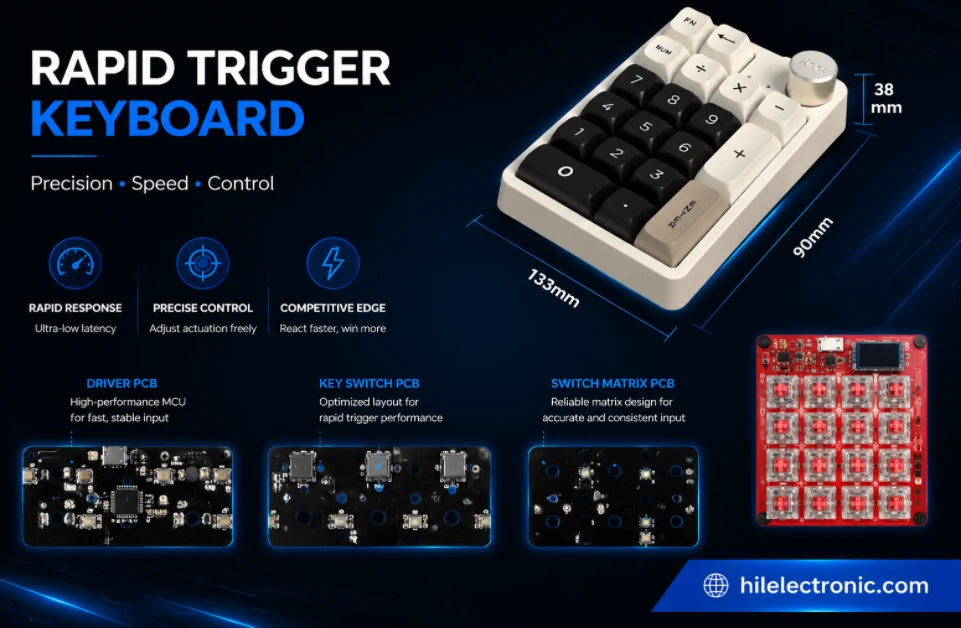
Rapid-trigger keyboards use analog position sensing and firmware-controlled actuation rather than a conventional binary switch matrix. Highleap Electronics supports this application as part of a much broader PCB manufacturing and PCB assembly service for consumer, industrial, IoT, communication and control electronics. Project scope can cover bare PCB fabrication, Hall sensor and analog front-end assembly, MCU and USB-C integration, RGB or wireless circuitry, firmware loading, calibration, traceable testing and final product integration from engineering prototypes to repeat production.
Because every key produces a changing analog signal, a rapid-trigger PCBA must be treated as a measurement system. Sensor placement, magnet geometry, analog power integrity, ADC range, PCB flatness, firmware revision, calibration fixtures and pass/fail limits all influence the final result. Highleap reviews the electrical, mechanical and test package together, while the customer retains control of the actuation algorithm, marketed latency claims and product-specific performance limits.
Rapid Trigger PCBA Buying and Performance Specifications
Highleap can manufacture a low latency keyboard PCB, adjustable actuation keyboard PCB or dynamic reset keyboard PCB as a controlled build-to-print product. An esports keyboard PCB manufacturing project normally needs tighter firmware, calibration and fixture control than a standard gaming board, so the quotation separates hardware manufacturing from customer-approved performance validation.
| Procurement item | Highleap supply and quotation basis |
|---|---|
| Product format | Bare rapid trigger PCB, assembled analog gaming keyboard PCBA, programmed module or finished keyboard integration. |
| Sensing method | Per-key Hall sensors or customer-defined analog sensing architecture with released switch and magnet geometry. |
| Performance controls | Noise floor, channel range, calibration curve, adjustable actuation, dynamic reset and USB behavior. |
| Assembly scope | Sensor array, analog front end, MCU, USB-C, RGB, connectors and optional wireless subsystem. |
| Test deliverables | Programming result, complete key response, calibration data, USB enumeration and customer-defined latency/performance report. |
| Prototype MOQ | Highleap’s prototype assembly program can start from 5 rapid-trigger PCBAs. When each unit requires mechanical travel, calibration data or latency capture, fixture investment and test cycle usually determine the most efficient pilot quantity. |
| Lead-time commitment | A rapid-trigger delivery date is issued after Hall sensors, MCU/ADC parts, firmware, golden units and the calibration station are ready. The PCBA lead-time guide explains the sourcing phases, while performance-test preparation is added to the project-specific plan. |
| Cost drivers | Sensor quantity, ADC/multiplexer architecture, fixture motion, data capture, test time, board size, RGB count and component availability. |
| Preferred quotation files | Provide Gerber/ODB++, drills, BOM, centroid, fabrication and assembly drawings, schematic, sensor/switch data, firmware, actuation/reset limits and the approved latency or calibration method. Standard package conventions follow the Highleap assembly-file specification. |
| Validation boundary | Highleap can execute an approved latency or actuation test but does not create unverified marketing claims or substitute the customer algorithm. |
Highleap’s rigid-board capability supports fine routing and multilayer construction, but rapid-trigger boards are approved around analog-channel spacing, power integrity, USB routing, sensor placement and fixture probing. The production stackup is therefore project-specific rather than a collection of maximum factory limits.
Rapid Trigger PCB Measurement and Control Requirements
Rapid Trigger changes the key state in response to movement rather than relying only on one fixed mechanical actuation and reset point. Wooting describes the feature as allowing a key to activate and reset as it moves, which depends on continuous position information: Wooting Rapid Trigger explanation. A production PCB therefore needs stable sensing, adequate sampling, controlled firmware and a repeatable mechanical stack.
Highleap can supply rapid trigger keyboard OEM hardware as bare PCBs, rapid trigger PCBA or a tested assembly. The released package should state whether the product is a wired low-latency controller, a magnetic analog keypad, or a complete gaming product with enclosure and key mechanism.
The underlying sensor-array manufacturing controls are detailed in Highleap’s Hall Effect keyboard PCB service page.
| System element | Performance dependency | Production evidence |
|---|---|---|
| Magnetic switch and sensor | Field strength, orientation, travel and distance | Approved components and mechanical drawing. |
| Analog measurement | Noise, reference stability, mux settling and ADC behavior | Raw-data and rail measurements on sample units. |
| Firmware processing | Calibration, filtering, actuation and reset logic | Approved binary, checksum and version-controlled limits. |
| USB interface | Enumeration, report behavior and power integrity | Host test and current measurement. |
| Mechanical assembly | Plate/PCB position and board flatness | Fit report and calibrated golden sample. |
| End-of-line fixture | Ability to exercise and verify every key | Correlation study and stored pass/fail results. |
Highleap can manufacture from a released customer design or support production engineering around an existing prototype. Product algorithms and claimed latency remain the customer’s responsibility unless a separate development scope is agreed.
Adjustable Actuation and Dynamic Reset Electronics
The electronics must obtain clean position information while LEDs, USB and other peripherals are active. Depending on the design, each key may connect to a dedicated ADC channel, an analog multiplexer, a sensor hub or another acquisition structure. The production review focuses on whether the actual component and routing choices can be assembled and tested consistently.
Switch and magnet compatibility should be frozen through the magnetic switch keyboard PCB review before performance tuning begins.
- sensor supply and reference decoupling near repeated Hall devices;
- ground-return control between analog sensing, digital switching and RGB current;
- mux source impedance and settling time before ADC sampling;
- MCU resources for scan, USB reports, profiles, lighting and calibration storage;
- test pads for power, programming, raw sensor access and fixture communication;
- ESD and connector protection that does not destabilise USB or power rails.
Highleap uses DFM review to identify routing bottlenecks, weak test access, unsupported footprints and panel risks before prototype fabrication.
Rapid Trigger Keyboard PCB Manufacturing Specifications
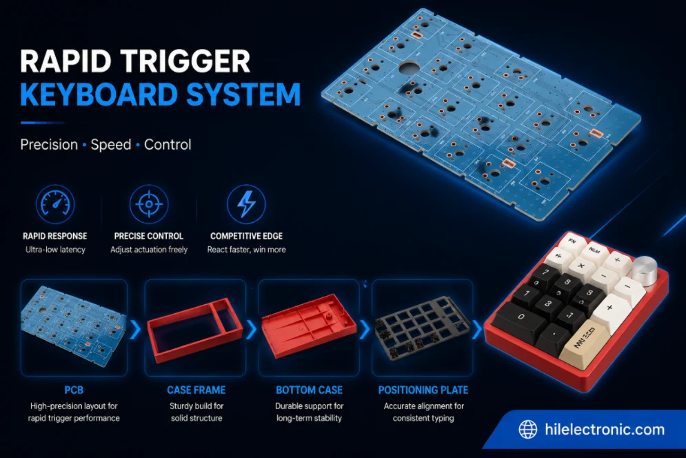
The following values are taken from the published Highleap rigid PCB capability table. They are factory-level limits, not a promise that every extreme can be combined in one build. Rapid-trigger designs are usually limited by analog layout, sensor pitch, USB integrity, flatness and assembly access rather than by the headline factory maximums.
| Manufacturing item | Published Highleap capability | Project condition |
|---|---|---|
| Maximum layer count | Up to 60 layers | Actual stackup is released after DFM review. |
| Minimum inner/outer trace and space | 2/2 mil | Copper weight, board size and process combination can change the practical limit. |
| Finished board thickness | 0.2–8.0 mm | Keyboard mechanical stack and connector height usually control the selected thickness. |
| Finished board size | 10 × 10 mm minimum; 22.5 × 47.5 in maximum | Panel utilisation, outline shape and assembly support must be reviewed. |
| Outline tolerance | ±0.1 mm | Critical switch, plate and enclosure interfaces should be dimensioned on the drawing. |
| Minimum SMT pad capability | 7 × 10 mil | Component package and paste aperture remain subject to assembly review. |
| Minimum BGA pitch | 7 mil | Final package assembly depends on pad design, stencil, via strategy and inspection plan. |
| Published impedance tolerance | ±5 Ω at ≤50 Ω; ±7% above 50 Ω | Relevant to USB, RF and other controlled-interconnect designs. |
| Published surface finishes | ENIG, ENEPIG, OSP, HASL, immersion silver/tin, hard gold and others | Finish is selected for solderability, contacts, cost and storage requirements. |
| Bow and twist | 0.3% | Thin or long keyboard boards require panel and fixture review to maintain flatness. |
The released stackup should provide predictable ground and power distribution. Highleap checks copper balance, routing around each sensor, USB differential routing when specified, local cutouts, screw locations and long-board handling. Controlled impedance can be included for USB or other interfaces through impedance-controlled PCB fabrication.
Low-Latency USB, Noise and Performance Validation
No responsible manufacturer should promise a universal latency number from PCB fabrication alone. Total response includes sensor acquisition, filtering, firmware scheduling, USB report timing, host behavior and switch mechanics. Highleap instead validates the electrical and manufacturing variables defined by the customer.
Highleap converts the approved method into a production station under the keyboard PCBA testing framework.
| Validation item | Method supplied or approved by customer | Manufacturing purpose |
|---|---|---|
| Raw key stability | Observe stationary values under lighting and power modes | Detect noise, solder or power problems. |
| Travel response | Move the switch through defined positions or fixture strokes | Confirm usable monotonic range and calibration. |
| Actuation/reset behavior | Run approved firmware and key-motion sequence | Verify production configuration. |
| USB operation | Enumeration, report and reconnect checks on target hosts | Detect connector, ESD or firmware issues. |
| Current and thermal behavior | Measure defined profiles and maximum-lighting mode | Confirm regulator and power-path margin. |
| Repeated input test | Cycle selected or all keys through automated fixture motion | Detect intermittent channels and mechanical variation. |
The test plan can be integrated into PCB functional testing. Performance limits must be realistic for the fixture, switch lot, sensor tolerance and mechanical assembly.
Calibration Fixtures and Golden-Unit Release
A rapid-trigger product needs more than a hand-pressed key test. Highleap can build or use a customer fixture that applies defined travel positions, reads raw values, writes calibration data and checks functional thresholds. The fixture design is quoted separately when it requires custom mechanics, electronics or software.
- Establish a golden unit: approve the switch, plate, PCB, firmware and measured response.
- Correlate fixture stations: compare repeated measurements and identify acceptable station variation.
- Lock calibration limits: define baseline, full-travel range, noise and channel-failure rules.
- Store revision data: record fixture, firmware and limit versions with the production lot.
- Review trend data: monitor yield and drift instead of relying only on final pass/fail.
- Retain failure samples: separate component, assembly, mechanical and software causes.
Highleap can load approved firmware using programming during PCBA processing and record the image revision for each production batch.
Representative Rapid Trigger Production Profiles
The following production profiles demonstrate how test scope changes with the intended product.
| Representative configuration | Typical hardware scope | Production and acceptance focus |
|---|---|---|
| Wired competitive input board | Per-key Hall sensors, USB-C, high scan rate and RGB | Calibration, noise capture, full-key exercise and customer-defined USB latency test. |
| Analog training keypad | Compact key set with adjustable actuation and data output | Channel linearity, mechanical travel fixture and recorded calibration values. |
| Wireless rapid-trigger product | Hall sensors, BLE/2.4 GHz, battery and wired fallback | Current, pairing, wired/wireless modes, calibration and radio-mode performance separation. |
Prototype MOQ, NPI Cost and Volume Delivery
The fastest safe schedule is staged. Initial prototypes confirm sensor and USB operation; engineering verification checks mechanical travel and calibration; NPI confirms the assembly and fixture; volume production follows the approved route. This prevents a large order from being committed before the key-response system has been proven.
Early builds can be scheduled through PCBA prototype production, followed by low-volume PCB assembly for pilot demand.
| Build phase | Primary output | Commercial decision |
|---|---|---|
| Prototype | Working PCBAs and raw-data access | Confirm architecture and component choices. |
| Engineering validation | Mechanical fit, calibration and firmware behavior | Approve product design or issue changes. |
| NPI / pilot | Process capability, fixture correlation and quality records | Release volume production. |
| Volume build | Controlled assembly and stored functional results | Ship against agreed lot acceptance. |
| Repeat order | Same approved revisions or documented changes | Protect product consistency and after-sales analysis. |
A committed lead time follows complete file review and component confirmation. Highleap can propose split shipments, customer-supplied critical parts or bare-PCB-first delivery when those options reduce program risk.
Why Highleap Is Suitable for Rapid-Trigger NPI
- The PCB, sensor assembly, firmware and fixture are released as one manufacturing system.
- Golden-unit and calibration-station approval can be completed before production scaling.
- Prototype quantities can use simplified fixtures while preserving the future data format.
- Component sourcing and sensor/MCU alternates are controlled through written approval.
- Lot records support investigation of noise, calibration or USB failures after shipment.
Rapid Trigger Keyboard PCB and PCBA FAQ
These long-tail questions address how rapid-trigger keyboard electronics differ from standard keyboard PCBs and what must be controlled before prototype or volume production.
What is a rapid trigger keyboard PCB and how does it work?
A rapid-trigger keyboard PCB measures the travel position of each key, commonly through Hall sensors and magnets, and uses firmware to change the reset point dynamically. Unlike a mechanical contact matrix, it continuously samples analog values so actuation, reset and sensitivity can be adjusted in software.
How is a rapid trigger PCB different from a standard mechanical keyboard PCB?
A standard keyboard usually detects an open or closed switch state. A rapid-trigger design needs stable sensor power, analog signal routing, ADC or multiplexer resources, per-key calibration data and firmware that converts sensor movement into key events. Manufacturing therefore requires more control over placement, noise, mechanics and test fixtures.
What determines adjustable actuation and dynamic reset accuracy?
Accuracy depends on the Hall sensor, magnet strength and polarity, sensor-to-magnet distance, switch travel, PCB and plate tolerances, ADC resolution, analog noise and the calibration algorithm. The production limit should be based on measured signal range and repeatability rather than only the nominal switch specification.
How are Hall sensors calibrated on a rapid trigger keyboard PCBA?
Calibration can record baseline and travel values for every key using a controlled fixture, approved switches or a golden mechanical assembly. The resulting constants may be stored in firmware, MCU memory or an external database. The method must define key travel points, temperature assumptions, retest rules and acceptable channel variation.
Can rapid trigger keyboard latency be tested during manufacturing?
USB polling, firmware processing and event timing can be checked with a customer-approved method, but a factory should not claim a universal latency number without a defined fixture, host, firmware build and measurement boundary. Electrical response testing and complete end-to-end key latency testing are different scopes.
What files are required for a rapid trigger keyboard PCB quotation?
Provide Gerber or ODB++, schematic, BOM, centroid, Hall sensor and magnetic switch data, plate and enclosure drawings, firmware, programming instructions, actuation and reset limits, calibration procedure, latency test method, quantity and expected reporting format. Physical switch or golden-unit samples are often useful.
Can a rapid trigger keyboard PCB also support RGB, USB-C and wireless modes?
Yes, but the added power, RF and firmware requirements must be considered alongside analog sensing. RGB switching noise, battery voltage variation, charger activity and wireless sleep states can affect sensor readings, so the design and test plan should evaluate the relevant operating modes.
What affects rapid trigger keyboard PCBA cost and minimum order quantity?
Cost is driven by sensor count, analog architecture, PCB size, component sourcing, calibration fixture complexity, per-unit test time, data storage and mechanical samples. Small prototype lots are possible, but a fixture-intensive calibration process may make a larger engineering batch more economical.
How does a rapid trigger keyboard prototype move into mass production?
The prototype stage proves the sensing range, firmware and mechanical relationship. NPI then freezes the PCB, BOM, approved switches, firmware, golden units, calibration equipment, test limits and traceability format. Highleap can manufacture and test to that released package; algorithm development or performance redesign is quoted separately.

Recommended Posts

TMM4 Filter PCB Manufacturing
TMM4 filter PCB manufacturing is controlled by the...

TMM3 PCB Manufacturing for RF Modules
TMM3 PCB manufacturing is most useful where the RF module...

TMM6 PCB Fabrication
TMM6 fabrication is the process-control page for a mid-Dk...

TMM10i PCB Fabrication and DFM
TMM10i PCB fabrication has a stronger DFM emphasis because...
How to get a quote for PCBs
Let’s run DFM/DFA analysis for you and get back to you with a report. You can upload your files securely through our website. We require the following information in order to give you a quote:
-
- Gerber, ODB++, or .pcb, spec.
- BOM list if you require assembly
- Quantity
- Turn time
For PCBA services, please provide your BOM (Bill of Materials) and any specific assembly instructions. We also offer DFM/DFA analysis to optimize your designs for manufacturability and assembly, ensuring a smooth production process.