
Taconic TLY-5 PCB Manufacturer for 77 GHz Radar and Antennas
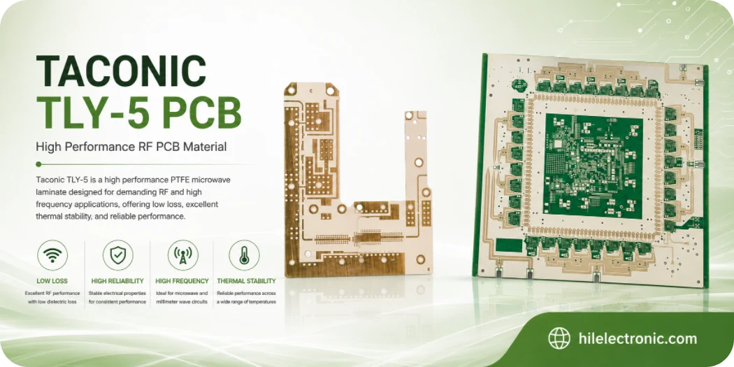
Highleap Electronics reviews, fabricates, and assembles Taconic TLY-5 PCBs for 77 GHz radar, antenna arrays, satellite and cellular RF, power amplifiers, and other low-loss mmWave circuits. The service is built around the finished RF structure: material thickness, copper profile, critical geometry, ground-via pattern, surface condition, assembly hardware, and the customer’s measurement method.
TLY-5 Antenna and mmWave PCB Manufacturing Support
Highleap can support TLY-5 antenna, radar, and mmWave boards with controlled impedance, via fences, plated transitions, multilayer or hybrid constructions, and RF-sensitive assembly requirements. Large panels, thin dielectric structures, unusual antenna geometries, or advanced interconnect are reviewed around the real RF target, laminate construction, panel stability, and process yield instead of being treated as standard catalogue limits.
Important: TLY-5 projects can be built from development samples through validated production volumes. When the application has special frequency, environmental, interconnect, or test requirements, Highleap reviews the manufacturing route before quoting the final construction.
Best fit
77 GHz radar antennas and feeds, mmWave launches, low-loss communication circuits, aerospace and satellite RF.
Main risk
At mmWave frequencies, small changes in line width, gap, thickness, edge position, finish, and local dielectric environment can move the result.
Highleap scope
Material and stackup review, PTFE fabrication, critical-dimension control, impedance/RF coupons, assembly, inspection, and customer-defined testing.
Quote inputs
Exact TLY-5 construction, copper, RF drawings, tolerances, stackup, holes, finish, quantity, forecast, BOM, assembly, and test files.
Can TLY-5 Meet Your 77 GHz or Antenna Requirement?
Taconic TLY-5 is a low-Dk, very-low-loss PTFE laminate reinforced with lightweight woven fiberglass. AGC publishes a nominal Dk of 2.2 ± 0.02 and a dissipation factor of 0.0009. The low dielectric constant supports relatively wide transmission lines, low dielectric loading, and efficient antenna or feed-network structures.
Strong fit
- 77 GHz automotive radar antennas and feeds;
- Ka-, E-, and W-band RF structures;
- satellite, cellular, aerospace, and low-loss interconnects;
- designs where antenna efficiency, phase control, and low mass matter.
Review another material when
- the design needs compact high-Dk resonators;
- temperature stability is more important than the lowest Dk;
- the board is a conventional digital multilayer with no RF-loss requirement;
- the woven-glass interaction cannot be accepted in the selected thin geometry.
At 77 GHz, the material name is only the starting point. Etched line width, gap, copper profile, dielectric thickness, glass orientation, antenna outline, launch geometry, surface finish, and enclosure spacing can shift the actual response. Highleap therefore quotes TLY-5 as a controlled RF structure, not as a generic PTFE board.
Highleap TLY-5 PCB Manufacturing Scope
Highleap can review TLY-5 designs for single- or double-sided RF boards, multilayer RF constructions, and mixed-material stackups. The project may include bare-board fabrication, component sourcing, SMT/through-hole assembly, shield and connector processing, and customer-defined RF or functional testing.
| Capability area | Review and manufacturing work | Release evidence |
|---|---|---|
| RF stackup | Confirm available TLY-5 thickness, copper profile, finished copper, bonding material, reference planes, mask treatment, and panel support. | Approved stackup and identified material risks. |
| Critical geometry | Separate antenna, launch, line, gap, edge, and connector dimensions from normal PCB tolerances; apply artwork compensation and inspection planning. | Measured critical dimensions or agreed first-article report. |
| PTFE drilling and plating | Review drilling support, hole-wall treatment, ground-via fences, plated-hole quality, routing, and thin-panel handling. | Microsection, plating, and final dimensional records as specified. |
| Controlled impedance/RF coupons | Build representative coupons using the same material, copper, and process; align the measurement method with the customer model. | Impedance, resonator, or other customer-defined results. |
| Assembly | Review solder paste, connector placement, shield cans, reflow, cleaning, board support, and RF test access. | AOI, X-ray, placement, cleanliness, and functional/RF records as required. |
Prototype feasibility does not guarantee volume yield. The quotation should identify which dimensions and tests will be controlled in both the first article and repeat production.
Stackup and Geometry Rules for mmWave PCBs
A 50-ohm line on a Dk 2.2 material is generally wider than the same line on a high-Dk laminate. Wider traces can be more robust to etch variation, but the electric field also extends farther into adjacent space. Copper keep-outs, board-edge distance, solder mask, housing metal, connectors, and nearby structures therefore become part of the RF model.
Inputs that must be frozen
- exact TLY-5 thickness and tolerance;
- copper type, starting copper, plated copper, and roughness model;
- microstrip, stripline, grounded coplanar, or antenna geometry;
- mask over the line, mask clearance, or no-mask requirement;
- critical line, gap, pad, slot, edge, and connector tolerances;
- glass-weave orientation and routing orientation where phase matching is sensitive;
- measurement reference planes, de-embedding, and acceptance limits.
For differential or parallel paths, a generic claim that TLY-5 “eliminates skew” is wrong. Woven reinforcement can still create local effective-permittivity variation. The actual risk depends on line width, pair spacing, route angle, laminate thickness, glass style, and length. Provide an allowed phase or time mismatch if it matters to the product.
TLY-5 Fabrication Process and Defect Controls
- Incoming material control: verify grade, thickness, copper, lot, storage, and approved bonding materials.
- CAM classification: mark RF-critical dimensions, calibration structures, antenna edges, and connector positions separately from ordinary features.
- Imaging and etching: use the selected copper weight and qualified process to establish compensation; inspect representative dimensions during first article.
- Drilling and activation: select tooling and hole-wall treatment for PTFE, with attention to dense ground vias and small plated holes.
- Plating and surface finish: control finished copper, pad shape, via quality, and the finish specified for soldering, bonding, storage, and RF loss.
- Routing and handling: support thin panels and protect antenna edges, slots, and outlines from deformation or burrs.
- Final verification: perform netlist test, critical-dimension inspection, microsection, impedance or RF coupons, and customer-defined acceptance tests.
Common failures include quoting the material without confirming thickness, applying FR-4 hole preparation, ignoring copper roughness, placing solder mask over an RF line without modelling it, and using an RF test fixture whose reference plane does not match the design model.
Where TLY-5 Creates Product Value
Automotive radar
The low Dk and low loss can support antenna arrays, feed networks, and mmWave launches. Product approval still depends on environmental range, radome and housing effects, antenna tolerances, connector or package transition, and a repeatable end-of-line test.
Aerospace and satellite RF
Low mass and low dielectric loading are useful, but the customer must define thermal cycling, vibration, outgassing or documentation requirements, connector attachment, and traceability. Material performance does not replace system qualification.
Power amplifiers and communication equipment
Low-loss lines and couplers can preserve RF power. Thermal performance must be engineered with copper, thermal vias, metal carriers, mounting, and airflow. TLY-5 is not selected primarily as a thermal conductor.
When TSM-DS3 or another grade may be preferable
A thermally stable ceramic-filled material may be better where temperature-dependent phase or resonance dominates. A nonwoven PTFE grade may be considered where glass-weave interaction is unacceptable. An equivalent cannot be approved from Dk and Df alone.
What Drives TLY-5 PCB Price and Delivery?
| Driver | Commercial effect | Required decision |
|---|---|---|
| Thin or uncommon laminate construction | Material procurement, MOQ, panel support, and handling may dominate the schedule. | Confirm approved thickness and alternate constructions before layout freeze. |
| 77 GHz critical dimensions | Extra CAM review, etch characterization, measurement, and yield control are required. | Identify only dimensions that truly control RF performance. |
| Via fences and small holes | Dense drilling, tooling wear, plating, and inspection add cost. | State via function and minimum necessary quantity. |
| Surface finish and solder-mask restrictions | Finish choice and selective mask handling affect process flow and RF geometry. | Specify the modelled surface condition. |
| RF coupon or product test | Fixtures, calibration, de-embedding, engineering time, and data reporting can exceed ordinary electrical-test cost. | Define limits and responsibility before quotation. |
| Assembly hardware | Connectors, shields, carriers, underfill, and precision placement can determine PCBA cost and yield. | Submit complete BOM, drawings, and mechanical tolerances. |
Highleap confirms lead time after material supply, manufacturing route, first-article evidence, assembly, and RF test are defined. A single “prototype lead time” without those conditions is not useful to a radar or antenna buyer.
RFQ Package for a TLY-5 PCB or PCBA
Send the fabrication data, netlist, drawing, complete stackup, exact TLY-5 thickness, copper foil, finished copper, impedance table, RF frequency range, critical dimensions, antenna/launch drawing, surface finish, mask treatment, hole and via-fence requirements, panelization, quantity, forecast, and delivery target.
For assembly, include the BOM, centroid, drawings, stencil or solder-volume requirements, connector and shield tolerances, reflow/cleaning restrictions, programming, test access, fixture information, RF limits, reference planes, and reporting format.
Highleap will return one of three useful outcomes: a manufacturable route, a request for missing information, or a recommendation to revise the material or geometry. A fast “yes” without identifying the mmWave acceptance method is not a meaningful capability answer.
Related resources: automotive radar PCB manufacturing, RF surface-finish selection, and RF PCB testing.
Commercial FAQ
Can Highleap manufacture a Taconic TLY-5 PCB for 77 GHz radar?
Highleap can review and quote 77 GHz TLY-5 projects. Approval depends on the exact antenna and launch geometry, laminate construction, copper, critical tolerances, environmental requirements, assembly design, and RF test method.
Can TLY-5 be used in a multilayer PCB?
Yes, with a compatible and qualified bonding construction. Pressed thickness, resin distribution, registration, drilling, plating, and CTE interaction must be controlled across the complete stackup.
Does TLY-5 automatically guarantee low insertion loss?
No. Total loss also depends on copper roughness, trace width, finish, current distribution, launches, vias, connectors, solder mask, and the full transmission-line structure.
What files are needed for a firm quotation?
Submit the full fabrication package, exact material and copper, stackup, impedance/RF criteria, critical dimensions, quantity, and delivery target. Include BOM, placement, assembly drawings, and test requirements for a PCBA quote.
Can you perform RF testing?
Customer-defined RF testing can be reviewed. Provide the fixture, calibration and de-embedding method, reference planes, frequency range, limits, and data format. Highleap can also propose representative coupon testing when appropriate.

Recommended Posts

Taconic RF 35 vs RO4350B PCB
Table of contentsRF-35 vs RO4350B Procurement and...

TMM4 Filter PCB Manufacturing
TMM4 filter PCB manufacturing is controlled by the...

TMM3 PCB Manufacturing for RF Modules
TMM3 PCB manufacturing is most useful where the RF module...

TMM6 PCB Fabrication
TMM6 fabrication is the process-control page for a mid-Dk...
How to get a quote for PCBs
Let’s run DFM/DFA analysis for you and get back to you with a report. You can upload your files securely through our website. We require the following information in order to give you a quote:
-
- Gerber, ODB++, or .pcb, spec.
- BOM list if you require assembly
- Quantity
- Turn time
For PCBA services, please provide your BOM (Bill of Materials) and any specific assembly instructions. We also offer DFM/DFA analysis to optimize your designs for manufacturability and assembly, ensuring a smooth production process.