
Fiber Optic Tether Spool PCB Supplier for UAV Systems

The fiber optic tether spool PCB is the control board that manages fiber payout, retrieval, and tension stability between a tethered drone and its ground station. While the optical data link PCB handles signal transmission and the flight controller handles aircraft movement, the spool PCB protects the mechanical condition of the fiber itself. That means maintaining stable tension, tracking deployed length, controlling spool speed, and preventing slack, overstress, or winding defects that can interrupt the optical link.
In real operation, this is a dynamic electromechanical control problem. Drone motion, wind disturbance, climb rate, descent rate, and spool inertia all affect fiber behavior in real time. The spool PCB must continuously coordinate motor drive, feedback sensing, optical monitoring, and safety logic to keep the tether within its usable tension window through launch, hover, maneuver, retrieval, and fault conditions.
Table of Contents
System Role and Control Objectives
The spool PCB is the active controller for the ground-side fiber reel. Its main task is simple to state but difficult to execute: keep the fiber taut enough to avoid slack, but low enough in tension to avoid excess attenuation, microbending, or breakage. In most tethered UAV systems, this means holding fiber tension in a narrow operating band while the aircraft moves unpredictably in three dimensions.
The board typically manages:
- Spool motor control for payout and retrieval
- Tension regulation using direct or estimated feedback
- Fiber length tracking for remaining tether awareness
- Optical health monitoring for loss, break, or degradation detection
- Status communication with the ground station controller
This makes the spool PCB a system-level controller rather than an isolated motor board. It has to react not only to motor and reel conditions, but also to changes reported by the UAV tether PCB and by the optical link itself. In a complete ground system, it often works alongside canister electronics or other tether-handling modules that manage dispensing, storage, or deployment state.
Tension Control and Length Tracking
The core control problem is closed-loop tension regulation. The spool PCB measures or estimates fiber tension, compares it with a target setpoint, and adjusts motor torque and spool speed accordingly. A practical controller must respond quickly to short disturbances such as climb bursts or gust loading, but it also has to avoid oscillation, overshoot, and slack formation.
Common feedback methods include:
- Load cell sensing at the exit guide for direct tension measurement
- Motor current or torque estimation using drive current and spool geometry
- Dancer arm feedback where a spring-loaded mechanism absorbs fast transients
In most systems, the controller is a PID-based or equivalent servo loop. The tuning must account for spool inertia, changing effective radius as fiber winds or unwinds, and the compliance of the tether itself. Anti-windup protection is essential, especially during slack events or when the motor reaches speed limits.
Length tracking is equally important. The operator needs accurate information about deployed fiber length, remaining reserve, and whether the current flight profile is approaching the reel limit. This is usually done with a motor or spindle encoder, combined with a winding-diameter model. In more advanced systems, length data also improves feedforward control, allowing the spool to anticipate payout or retrieval demand instead of reacting only after tension changes.
Motor Drive, Power, and Safety Hardware
The spool motor is normally the highest-power subsystem on the board. Depending on spool size and retrieval speed, the motor may range from tens of watts to several hundred watts. That requires a motor drive stage capable of precise torque control, smooth low-speed behavior, and reliable fault response.
Most advanced spool PCBs use a BLDC motor with a three-phase inverter and either trapezoidal commutation or field-oriented control. For tether management, FOC is usually preferred because it provides smoother torque at low speed, which directly reduces tension ripple on the fiber.
The power and safety section usually includes:
- Gate driver and MOSFET bridge sized for spool acceleration and steady-state operation
- Bulk capacitance near the power stage to absorb current transients
- Current sensing for torque estimation, drive control, and hardware protection
- Reverse polarity and surge protection for field-installed systems
- Emergency stop hardware that disables the motor independently of firmware
- Over-tension and over-current protection that can trigger even if the processor is delayed or faulted
In practical terms, the safest design is always dual-layered: software handles normal regulation and graceful derating, while dedicated hardware comparators and inhibit paths handle worst-case conditions. For systems that also integrate hybrid power-and-fiber tethering, the design considerations overlap with those in the fiber pay-out spool board architecture, where mechanical handling and electrical robustness must coexist.
Optical Monitoring and Ground Station Integration
The spool PCB is not only a motion controller. It is also an important diagnostic node in the tether system. By monitoring received optical power and comparing it with the transmitted signal budget, the board can help detect excessive bend loss, emerging damage, connector degradation, or complete fiber break.
Typical optical and system-level functions include:
- Receive-power monitoring through a photodiode tap or transceiver diagnostics
- Link quality trending to identify degradation before failure
- Fault signaling when optical power drops below threshold
- Operator reporting for tether length, tension, motor status, and optical health
Communication to the ground station is usually handled over CAN, RS-485, or Ethernet, depending on the rest of the ground system. The spool PCB should export clean, actionable status rather than raw sensor noise: current tension, remaining fiber, motor state, optical power, and active fault conditions.
Because the board sits in a noisy electromechanical environment, optical monitoring cannot be treated as a purely digital task. It has to be protected from motor-drive noise, supply ripple, and ground contamination. These board-level concerns are closely related to the practices used in secure drone communication hardware, where link integrity and trusted signal handling are both central to system reliability.
PCB Layout, Manufacturing, and Functional Testing
The spool PCB combines power electronics, precision analog, encoder interfaces, optical diagnostics, and communications on one board. That mix makes layout discipline critical. The highest-current switching paths must be tightly contained, while the analog front end, timing circuits, and optical monitor need a cleaner environment.
Key layout priorities include:
- Clear partitioning between motor power, digital control, and analog sensing zones
- Short high-current loops in the gate driver and bridge section
- Continuous ground reference with controlled return paths
- Filtered boundary crossings where signals move between noisy and quiet domains
- Careful connector placement for motor leads, sensor lines, and operator interfaces
Because motor switching can easily contaminate the analog and optical sections, the board should follow the same physical separation principles used in anti-interference UAV PCB design. In systems operating near sensitive RF or navigation hardware, the same EMC discipline also aligns with GPS-denied drone electronics, where avoiding self-generated interference is essential.
From a manufacturing standpoint, this is a mixed-technology board. It may include fine-pitch SMT devices, larger power components, rugged connectors, and heavy-current sections on the same assembly. Functional testing should go beyond continuity checks. A realistic production test flow should verify:
- motor commutation and driver behavior under load,
- encoder counting accuracy,
- tension control response,
- optical monitoring thresholds,
- and all hardware safety triggers.
Highleap supports this type of product with board fabrication and assembly processes suited to mixed analog, digital, and power designs. For projects that also need sourcing coordination and production planning, the workflow can extend into full engineering review and manufacturing support.
FAQ
What does a fiber optic tether spool PCB actually control?
It controls spool motor behavior, regulates fiber tension, tracks deployed length, monitors optical health, and reports system status to the ground station.
Why is tension control more difficult than simple motor control?
Because the spool is reacting to drone motion, wind disturbance, fiber compliance, and changing spool radius in real time. The board must hold tension in a narrow safe range without creating slack or overstress.
Can the spool PCB detect a fiber break?
Yes. This is commonly done through receive-power monitoring or transceiver diagnostic data, combined with fault thresholds and operator alerts.
Why is PCB layout so important on this board?
Because the design combines high-current motor switching with precision analog sensing and optical monitoring. Poor layout can create noise coupling, false readings, and unstable control behavior.
How is a spool PCB different from heavier winch or drum electronics?
A spool PCB is optimized for low-tension, fast-response fiber management in UAV tether systems, while drum or winch electronics are often designed for higher mechanical loads and different duty conditions. The fiber drum electronics PCB is closer to that heavier-duty class.

Recommended Posts

Rogers TMM6 PCB Manufacturing for Microwave Filters
Table of contentsWhy Microwave Filter Designers Use...

Taconic fastRise 27 Prepreg PCB Bonding and HDI Fabrication Service
Table of contentsWhat fastRise 27 Is—and What You Are...
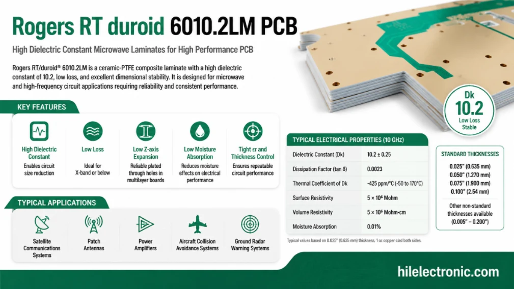
Rogers RT/duroid 6010.2LM PCB Manufacturer and Fabrication Service
Table of contentsIs RT/duroid 6010.2LM the Right Material...
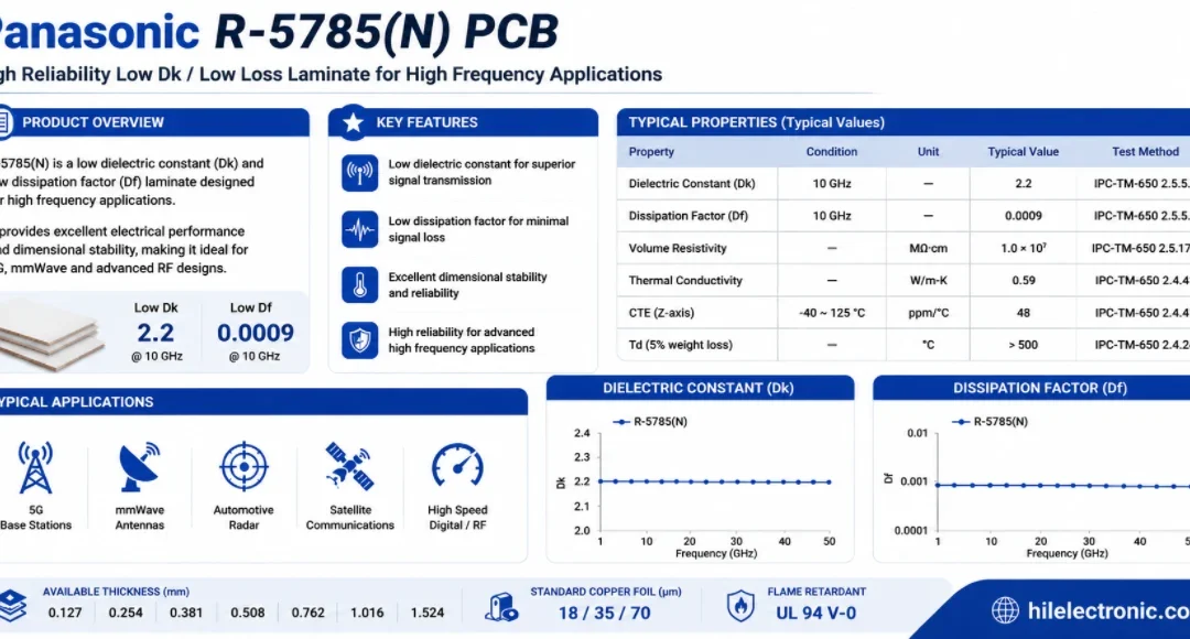
Panasonic R-5785(N) MEGTRON 7 PCB Manufacturer and Fabrication
Table of contentsWhen a Design Should Move to R-5785(N) /...
How to get a quote for PCBs
Let us run DFM/DFA analysis for you and get back to you with a report.
You can upload your files securely through our website.
We require the following information in order to give you a quote:
-
- Gerber, ODB++, or .pcb, spec.
- BOM list if you require assembly
- Quantity
- Turn time