
Fiber Optic Tether PCB UAV Design and Communication System

Fiber optic tether PCB UAV design refers to the onboard interface board used when a tethered UAV system includes optical fiber as part of its communication link. In practical tethered-drone cable design, electrical power is typically delivered through copper conductors, while optical fibers may be added to the same tether when high-bandwidth data transfer, secure communications, or low-interference signal transmission are required. This makes the board an optical communication interface within a broader tethered UAV cable system rather than a standalone power-entry module.
In this configuration, the board sits at the boundary between the tether cable and the drone’s internal electronics. It converts between optical signals in the tether-side fiber and the electrical data interfaces inside the aircraft, while maintaining signal integrity under vibration, cable movement, tension variation, and spool-related mechanical stress. In systems that use a multipurpose tether, the board may coexist with a separate onboard power-conversion module that handles high-voltage power delivered through the cable conductors.
Table of Contents
- Fiber Optic Tether PCB UAV as a System Boundary
- Optical Signal Path: From Tether Fiber to Onboard Electronics
- Relationship to Power Tether Architecture
- Integration with Spool and Tether Management Systems
- Continuous Link and Tether Health Monitoring
- Mechanical Design at the Fiber Entry Interface
- Material, Environmental Hardening, and Assembly
Fiber Optic Tether PCB UAV as a System Boundary
In system architecture terms, a fiber optic tether PCB UAV functions as the communication boundary between the tether-side optical path and the drone’s onboard electronics. This role becomes important when a tethered UAV cable is used not only for power delivery but also for communications. On the external side, the board interfaces with a cable exposed to movement, bending, wind load, tension changes, and spool dynamics. On the internal side, it connects to processors, video paths, communication devices, or mission electronics that require stable and predictable signal behavior.
This is why the board is often implemented as a dedicated interface instead of being merged directly into the main flight controller. The tether-side connector, optical routing path, and mechanical cable-entry structure impose requirements that differ significantly from the rest of the onboard electronics. The broader system context for this class of hardware is covered in the fiber optic drone PCB architecture overview.
Optical Signal Path: From Tether Fiber to Onboard Electronics
The incoming signal reaches the UAV through an optical fiber integrated into the tether cable and terminated at a connector or protected fiber-entry interface. Depending on the platform, this may use a standard commercial optical connector or a more ruggedized structure designed for harsh environments. On the board, the received optical signal is converted into electrical form by the receiver path and then passed into the drone’s communication or processing electronics.
In the opposite direction, onboard data is serialized or otherwise prepared by the communication path, converted into modulated light by the transmitter circuitry, and coupled into the tether-side fiber. The board therefore supports bidirectional data flow while controlling insertion loss, reflection sensitivity, and interference around the optical interface.
Key layout requirement
The optical interface section should use controlled-impedance routing, continuous reference structure, careful via management, and sufficient separation from noisy digital or switching regions. The exact routing strategy depends on stack-up, connector structure, data rate, and channel-loss budget, but the core objective is always the same: preserve timing margin and overall link robustness.
The same board-level signal-integrity principles used in other optical UAV interface designs still apply here, including impedance control, reference continuity, and careful transceiver-side decoupling. These fundamentals are also discussed on the drone optical data link board page.
![]()
Relationship to Power Tether Architecture
A fiber optic tether PCB UAV should not be confused with the main airborne power-conversion stage of a tethered drone. In many tethered UAV systems, electrical power is sent up the cable through copper conductors, often at elevated voltage to reduce cable weight and transmission loss. The aircraft then uses a dedicated power module to convert that input into lower-voltage rails suitable for onboard electronics.
When optical fibers are also included in the tether, the role of the fiber optic tether PCB is different. It is primarily responsible for communication, control, or data-transfer functions at the optical boundary. In a multipurpose tether, the electrical power path and the optical communication path may coexist in the same cable, but they remain distinct subsystems on the aircraft side. This distinction is important because the communication interface board and the power-conversion hardware do not have the same design priorities.
In short-range tethered drones, the tether may be mainly an electrical cable or cable rope optimized for lightweight power delivery. In higher-capability or multi-purpose systems, optical fibers may be added to support high-bandwidth data, low-interference communications, or other advanced link requirements.
Integration with Spool and Tether Management Systems
Many tethered UAV systems use a spool, reel, or related cable-handling structure to manage deployment and retrieval. Where optical fibers are integrated into the tether, the board does not operate around a static cable entry alone. It also has to remain reliable while the tether is guided, tensioned, reeled, or redirected by surrounding hardware.
In systems with a fiber optic spool or related deployment hardware, the board may sit near the cable handoff point where bend control, routing stability, connector protection, and mechanical retention are all critical. That is why this board category often connects naturally to a fiber optic tether spool PCB or, on the support side, a fiber optic canister PCB.
Tether management systems can also influence the onboard interface environment. These systems may monitor cable force, adjust slack, and compensate for changing aircraft or base-station position. Even when the fiber optic tether PCB is dedicated to communications rather than power handling, it still has to tolerate the mechanical effects introduced by cable-management behavior during operation.
Continuous Link and Tether Health Monitoring
In more advanced implementations, the board may also monitor the condition of the optical link and the mechanical state of the tether path during operation. This helps detect degradation before total failure and supports more reliable mission behavior.
| Parameter | Measurement method | What degradation indicates |
|---|---|---|
| Received optical power | Optical receiver diagnostics or dedicated monitoring circuitry | Connector contamination, excessive bending, or developing fiber damage |
| Link error counters | PHY, transceiver, or decoder diagnostics | Signal-quality degradation before total link loss |
| Tether tension | Strain gauge or load-sensing mechanism at the attachment point | Excessive wind load, spool malfunction, snag, or abnormal cable-management behavior |
| Fiber path continuity | Link-state diagnostics or continuity-related monitoring logic | Intermittent connection, connector instability, or fiber break risk |
Monitoring data can be sent to the flight controller, mission computer, or support electronics for warning, fault handling, or maintenance tracking. A gradual decline in optical performance may indicate contamination or growing bend stress, while an abrupt change can trigger protective procedures. Complementary support functions on the ground side may be handled by the canister and ground-station electronics.
Mechanical Design at the Fiber Entry Interface
The cable-entry and optical-connector region is one of the most mechanically sensitive parts of the interface. It must preserve alignment and path stability under vibration, thermal expansion, cable movement, and any dynamic loading introduced by reeling, slack adjustment, or changing tether tension.
Board-level provisions typically include: rigid connector support, reinforced mounting around mechanical anchor points, strain relief that prevents cable loads from acting directly on the optical termination, and careful placement of the cable-entry geometry so the fiber path remains stable in operation. If conformal coating is used, selective masking is required to keep optical mating surfaces clean and functional.
Fiber bend radius is another critical constraint. The cable-entry path must remain above the fiber’s specified minimum bend radius, so the PCB connector location, guide structure, and nearby mechanical features must preserve that geometry across the full operating range of the system.
Material, Environmental Hardening, and Assembly
Tethered UAV cable systems often operate outdoors in changing conditions involving temperature variation, humidity, dust, and mechanical exposure. The tether-side PCB may sit near the cable-entry zone, where contamination risk and physical stress are higher than in more protected electronics compartments.
Material selection guidance
Material selection should reflect thermal range, humidity exposure, corrosion risk, connector durability, and long-term dimensional stability. High-Tg laminates are common, while surface finish and coating chemistry should be chosen to balance corrosion resistance, process compatibility, and optical-interface cleanliness. Depending on the environment, this may include high-Tg FR-4, polyimide-based materials, ENIG or hard-gold finishes, and acrylic or polyurethane conformal coatings.
Manufacturing may require controlled-impedance fabrication for the optical high-speed section, reinforced mounting structures, mixed-technology assembly, and selective masking around optical and connector-critical regions. Where the overall system also partitions control logic through the optical path, the board may overlap conceptually with a fiber-guided UAV control PCB depending on how communication and control functions are arranged.
Highleap Electronics manufactures UAV tether circuit boards for commercial and defense platforms, supporting precision signal routing, ruggedized interface design, and application-specific assembly requirements. For new projects, design data and system requirements can be submitted through the engineering review form for manufacturability review and quotation.

Recommended Posts

Per-Key RGB Keyboard PCB Manufacturer & LED Assembly
A per-key RGB keyboard PCB manufacturer must control far...

Ortholinear Keyboard PCB Manufacturer | Custom Grid Layout
An ortholinear keyboard PCB manufacturer must preserve a...
Keypad PCB Assembly Manufacturer | Custom Control Keypads
A keypad PCB assembly manufacturer may be building a...
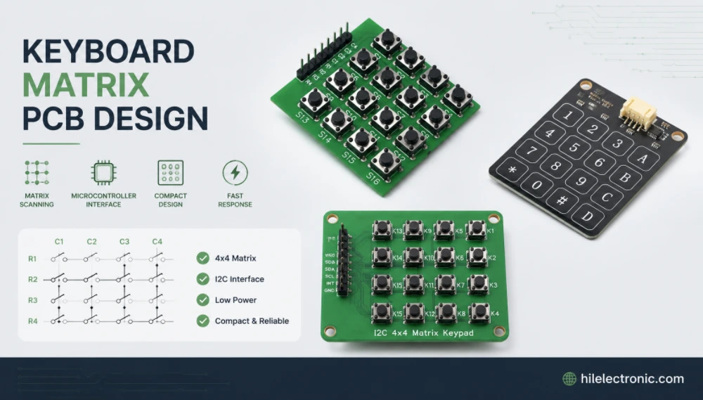
Keyboard Matrix PCB Design & Manufacturing | Anti-Ghosting
Keyboard matrix PCB design converts a large number of...
How to get a quote for PCBs
Let us run DFM/DFA analysis for you and get back to you with a report.
You can upload your files securely through our website.
We require the following information in order to give you a quote:
-
- Gerber, ODB++, or .pcb, spec.
- BOM list if you require assembly
- Quantity
- Turn time
In addition to PCB manufacturing, we offer a comprehensive range of electronic services, including PCB design, PCBA (Printed Circuit Board Assembly), and turnkey solutions. Whether you need help with prototyping, design verification, component sourcing, or mass production, we provide end-to-end support to ensure your project’s success. For PCBA services, please provide your BOM (Bill of Materials) and any specific assembly instructions. We also offer DFM/DFA analysis to optimize your designs for manufacturability and assembly, ensuring a smooth production process.