
Keypad PCB Assembly Manufacturer | Custom Control Keypads
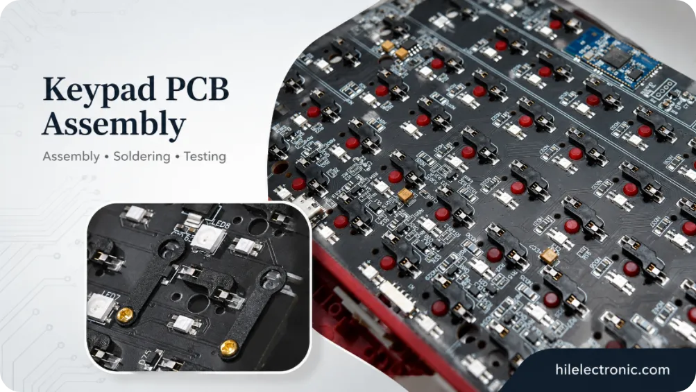
A keypad PCB assembly manufacturer may be building a numeric keypad, machine control keyboard, access panel, medical-device interface or equipment subassembly—not simply a small mechanical keyboard. The PCB can combine keys with encoders, displays, LEDs, buzzers, connectors, cable harnesses, relays or communication circuits.
Highleap Electronics supplies bare keypad PCBs, SMT/THT-assembled PCBAs, programmed controllers, tested modules and optional enclosure or cable integration. Input technologies can include mechanical switches, tact switches, membrane connectors, capacitive touch electrodes or mixed controls.
Simple keypads often use two copper layers, while more complex control panels may require multilayer routing. Components can be populated on one or both sides. Customers can start a quote with a key count, product photo and quantity; no PCB schematic is required.
Start a Keypad PCB Assembly Quote
Tell us the keypad application, approximate number of keys or controls, expected quantity and whether you need PCB, PCBA, programming or complete module assembly. A photo, sample or available files can be sent if convenient. No schematic is required for the initial quotation.
Keypad Types, Applications and Buying Inputs
| Product type | Typical functions | Manufacturing priorities |
|---|---|---|
| Numeric keypad PCB | Digits, enter, arithmetic and navigation | Key feel, legends, USB/serial interface and full-key test. |
| Industrial control keypad | Function keys, indicators and machine commands | Durability, connector retention, traceability and lifecycle supply. |
| Equipment panel PCB | Buttons, encoders, display and status LEDs | Mechanical integration, cable routing and mixed assembly. |
| Programmable keypad/macropad | Layers, shortcuts, RGB and encoders | Firmware revision, bootloader and configurable keymap test. |
Keypad PCB Assembly Buying Guide
The first inquiry can be based on a reference product, front-panel drawing or functional description. Exact BOM, placement and mechanical release data are confirmed after the project scope is qualified.
| Keypad category | Typical electronics | Main production risk |
|---|---|---|
| Numeric keypad | Matrix keys, status LEDs, USB or cable output. | Keymap, connector pinout and enclosure alignment. |
| Machine control keypad | Keys, encoders, displays, buzzer, protected field interface. | Mechanical loading, cable faults and industrial environment. |
| Access/security keypad | Touch/mechanical input, backlight, reader/interface electronics. | Outdoor exposure, ESD and tamper-related product requirements. |
| Medical/equipment panel | Sealed keys or touch, indicators and host interface. | Cleaning compatibility, traceability and system validation. |
Input Technologies, Electrical Architecture and Host Interfaces
A small keypad may expose a raw row/column matrix to the host, while a complete keypad PCBA may contain its own MCU and send USB HID, serial, CAN or custom messages. The quotation should distinguish these architectures because they have different component, firmware and test requirements.
Raw matrix keypad
The host scans the rows and columns. The keypad assembly may contain only switches, diodes, LEDs and a connector. Pinout control and cable testing are critical because one swapped wire can move an entire row or column.
Intelligent keypad module
An onboard controller handles debounce, key mapping, indicators and communication. Production then includes programming, version control and host-interface testing. The module can be easier for the equipment manufacturer to integrate but has a more complete PCBA cost.
Mixed control panel
Industrial machine-control panels may combine keypad input with analog controls, relays or isolated communication. These should be treated as custom control electronics rather than ordinary keyboard boards.
A keypad can use mechanical switches, tact switches, membrane contacts, capacitive electrodes or a mixed architecture. A row-column matrix reduces MCU pin count, while direct GPIO may simplify very small or safety-separated inputs. Diode use, debounce and rollover requirements should follow the application rather than keyboard conventions copied from another product.
- Mechanical and hot-swap designs require exact switch/socket and plate data.
- Tact-switch panels require force, height, cap and lifecycle definition.
- Membrane tails require connector pinout and contact resistance limits.
- Capacitive keys require overlay, shielding and calibration requirements.
Front-Panel, Display, Encoder and Mechanical Integration
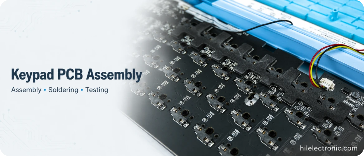
Mechanical switches, tact switches, membrane tails and capacitive touch each need a different PCB interface. A membrane keypad may terminate through an FFC/FPC connector or conductive tail; a capacitive panel depends on electrode and overlay calibration; a mechanical keypad requires switch/plate alignment and possibly hot-swap sockets.
The PCB should be reviewed with the front panel, not as an isolated rectangle. Key centers, display windows, encoder shafts, LED light pipes, mounting holes and connector exits must share one datum. A first-article fit check is especially important when the enclosure supplier and PCBA supplier are separate.
Many control keypads combine keys with OLED/LCD displays, rotary encoders, buzzers, backlighting, cable harnesses or panel connectors. Component height and keepout must be checked in 3D. Cable orientation, latch access and strain relief should be documented so the PCBA can be assembled and serviced inside the equipment.
Two-layer PCBs are common, but added displays, communication interfaces, RGB or constrained routing may require more layers. Components may be assembled on both sides even when the bare PCB is two-layer; these specifications should not be confused.
Displays, Encoders, Harnesses and Secondary Assembly
Displays and indicators
OLED/LCD modules may be soldered, socketed or cable-connected. Height, viewing window, polarity and firmware initialization must be checked. LEDs can require light pipes or diffusers, so optical alignment is part of mechanical release.
Encoders and controls
Rotary encoders and joysticks apply repeated mechanical load. Through-hole anchors, board support and knob/enclosure clearance matter. Their detent count and push-switch behavior should be included in the functional test.
Cables and connectors
PCB cable and harness assembly introduces pinout, crimp, strain relief and mating risks. Highleap can test cable continuity and interface operation as part of the module, while the production specification identifies whether cables are customer-supplied, sourced or assembled.
Mechanical Loads, Operator Use and Enclosure Fit
Controls operated by hand transfer force through key stems, encoder shafts and panel hardware. PCB mounting should prevent bending that cracks solder joints or changes tactile feel. Heavy displays and connectors need separate support where appropriate.
- Verify key travel and panel aperture after final assembly.
- Keep mounting hardware clear of traces, electrodes and bottom-side components.
- Control torque for panel nuts and encoder bushings.
- Provide strain relief for cables leaving the enclosure.
- Check labels and legends against firmware behavior.
Keypad PCBA Manufacturing and Functional Testing
- Review the product description, front-panel geometry, interface and quantity for quotation.
- Confirm PCB, BOM, placement, firmware and mechanical release data before production.
- Fabricate the PCB and complete bare-board electrical testing.
- Inspect incoming switches, displays, connectors, overlays and custom parts.
- Complete SMT assembly and AOI, followed by THT, selective or hand soldering where specified.
- Program the approved bootloader, application and product identity when required.
- Test every input, display, indicator, encoder, cable and host interface included in the scope.
- Complete panel, cable or enclosure integration and final fit checks when ordered as a module.
Keypad Functional Test Fixtures and Golden-Unit Comparison
A keypad functional test fixture may press physical keys, stimulate matrix inputs or communicate through the finished host interface. The method should match the input technology and order volume. A revision-controlled golden unit is useful for display appearance, buzzer level, encoder direction and enclosure fit, but it should not replace released drawings and acceptance limits.
| Test item | Acceptance example | Record or failure isolated |
|---|---|---|
| Every key or control | Correct logical code with no duplicate or missing event. | Position-by-position result; switch, matrix or firmware-map fault. |
| Display and indicators | Correct segment, pixel, color, text and brightness mode. | Functional result or controlled golden-unit comparison. |
| Encoder or joystick | Correct direction, detents, push switch and range. | Event count and direction. |
| Host interface and cable | Stable communication at the defined voltage and protocol. | Interface log; connector, transceiver, cable or firmware fault. |
| Mechanical fit | Controls, windows and connectors align with the released enclosure. | CAD, component-height or assembly-tolerance issue. |
Failure Prevention, Cost, Supply Models and Production Records
| Problem | Likely cause | Control |
|---|---|---|
| Wrong character or command | Keymap, connector pinout or firmware variant mismatch. | Coordinate-based functional test with released firmware. |
| Key does not align with front panel | Datum, tolerance or enclosure revision mismatch. | Overlay CAD and first-article panel fit. |
| Encoder feels loose | Insufficient anchor solder or unsupported board. | Review PTH fill, mechanical support and knob load. |
| Display works intermittently | Connector contact, module soldering, power margin or firmware timing. | Separate interface, power and software diagnosis. |
| Cable fails after installation | Wrong crimp, bend radius, strain relief or pinout. | Continuity plus installed mechanical inspection. |
Supply Models, Customization, MOQ and Cost Drivers
Highleap can source standard components, assemble customer-supplied custom parts or use a mixed supply model. Responsibility for overlays, displays, molded keys, proprietary connectors and other appearance-critical parts should be defined before production release.
Cost depends on key count, input technology, display and control content, SMT/THT operations, cable work, enclosure or box-build integration, programming and test time. Prototype and low-volume builds are practical for specialized equipment, while stable repeat orders benefit from panelization, component purchasing, setup reuse and fixture amortization.
Long-lead custom parts should be approved early enough for pilot validation. Any substitute affecting mechanical fit, firmware, optical appearance or environmental performance requires customer approval before it enters production.
Keypad PCBA Production Records
When included in the project scope, production records can cover first-article front-panel fit, AOI, PTH solder inspection, firmware revision, every-key or control output, display and interface test, harness continuity and serialized labels. The record set should match the supplied level: bare PCB, assembled PCBA, programmed module or complete keypad assembly.
Keypad PCB Assembly FAQ
What is included in keypad PCB assembly?
PCB fabrication, component sourcing, SMT/THT assembly, programming, full-key testing and optional cable or enclosure integration according to the agreed project scope.
Can a keypad use mechanical, membrane or capacitive inputs?
Yes. Each technology requires a different footprint, mechanical stack, controller and test method.
How are all keys tested?
A fixture or test program activates every fitted input and compares the host output with the released logical map.
Can Highleap build small and large quantities?
Prototype and low-volume builds can be quoted, followed by pilot and mass-production pricing once the design, BOM and test route are stable.
Discuss a Custom Keypad PCB Assembly
Provide the application, approximate key/control count, quantity and whether the project needs PCB, PCBA or a complete module. A photo or sample is enough to start; no PCB schematic is required for the initial quotation.

Recommended Posts

TMM4 Filter PCB Manufacturing
TMM4 filter PCB manufacturing is controlled by the...

TMM3 PCB Manufacturing for RF Modules
TMM3 PCB manufacturing is most useful where the RF module...

TMM6 PCB Fabrication
TMM6 fabrication is the process-control page for a mid-Dk...

TMM10i PCB Fabrication and DFM
TMM10i PCB fabrication has a stronger DFM emphasis because...
How to get a quote for PCBs
Let’s run DFM/DFA analysis for you and get back to you with a report. You can upload your files securely through our website. We require the following information in order to give you a quote:
-
- Gerber, ODB++, or .pcb, spec.
- BOM list if you require assembly
- Quantity
- Turn time
For PCBA services, please provide your BOM (Bill of Materials) and any specific assembly instructions. We also offer DFM/DFA analysis to optimize your designs for manufacturability and assembly, ensuring a smooth production process.