
Fiber-Guided UAV Control PCB Manufacturing and PCBA

What distinguishes this board from a conventional flight controller is not processing power but the demands of the optical interface combined with hard real-time requirements. The guidance command loop — from operator input to actuator movement — must close within the aerodynamic response time of the platform. For surveillance drones with slow, deliberate flight profiles, 40–50 ms is acceptable. For fast tactical platforms executing terminal maneuvers, the budget may be under 10 ms. These timing requirements drive every architecture decision: fiber interface, processor choice, actuator output method, and failsafe behavior.
Get a Fiber-Guided Control PCB Quote
Quick answer
A fiber-guided UAV control PCB processes guidance commands received through dispensed optical fiber, converts optical signals to flight control outputs with sub-50 ms latency, returns video and telemetry through the same fiber via WDM, and executes deterministic failsafe behavior on fiber loss. Descended from FOG-M missile heritage, the design prioritizes command latency, single-use or limited-reuse reliability, and hard real-time determinism. It differs from tether spool boards in that the fiber is never retrieved — the platform dispenses from a canister at flight speed and the fiber trail is left behind.
Table of Contents
- Heritage: From FOG-M to Modern Fiber-Guided Drones
- System Architecture and Board Role
- Guidance Command Path and Latency Budget
- Sensor Feedback and Video Return Path
- Fiber Dispensing Monitoring
- Failsafe Design for Fiber Loss
- Processor and RTOS Selection
- Power Architecture for Single-Use Platforms
- Guided vs. Tethered: Design Differences
- Manufacturing and Qualification
- FAQ
Heritage: From FOG-M to Modern Fiber-Guided Drones
The BGM-71 TOW missile (1970s) used copper wire dispensed from both launcher and missile during flight, with guidance signals transmitted over the wire. Range was limited by wire tensile strength and electrical signal attenuation — typically under 4 km. In the late 1970s and 1980s, defense research programs explored replacing copper with optical fiber for two reasons: fiber’s gigabit bandwidth supported video return from a camera in the missile seeker, and fiber’s immunity to electromagnetic interference addressed concerns about wire-guided systems being jammed by high-powered microwave emitters.
The Fiber Optic Guided Missile (FOG-M) program demonstrated the concept but was cancelled before production. The technology it validated — dispensed fiber from both the launch platform and the munition, with optical guidance commands and video return — became the foundation for modern fiber-guided drone architectures. The key difference is that today’s platforms are drones rather than one-way munitions: they carry cameras and sensor suites for ISR rather than warheads, they may loiter rather than fly directly to a target, and in some configurations they can be recovered and reused.
The modern fiber-guided control PCB inherits the fundamental signal architecture from FOG-M — optical command forward, video return, passive fiber dispensing — and adapts it to drone flight profiles, current processor architectures, and the availability of commercial optical fiber and transceiver technology at costs that were not available in the 1980s.
System Architecture and Board Role
The fiber-guided system consists of: ground station (operator console + fiber coil + optical transmitter/receiver) → dispensed fiber → airborne control PCB → flight actuators + camera + sensor payload. The control PCB is the sole interface between ground and air for the entire mission duration. Its optical interface must receive commands reliably, its processor must execute them in real time, and its actuator drivers must produce clean, low-latency outputs to the flight control surfaces or motors.
Unlike a tethered drone where the fiber is managed by a bidirectional spool system, a fiber-guided platform dispenses from a canister passively — the fiber pays out as the drone moves, and when the canister is empty, communication ends. The canister electronics interface is managed on the fiber optic canister PCB, which monitors remaining fiber, tension at the exit guide, and dispensing rate. The control PCB receives status data from the canister board over an inter-board bus and uses this for mission management decisions.
Board partitioning: some designs integrate the optical interface, processor, actuator outputs, and canister monitoring on a single board. Others split the optical interface onto a dedicated optical data link board connected to the control board via a high-speed connector. The integrated approach saves weight and connector count. The split approach allows independent optimization of the analog-heavy optical interface and the digital-heavy control function, and may simplify EMC between the two.
Guidance Command Path and Latency Budget
The guidance loop runs: operator input → ground control software → optical encoding → fiber → airborne optical receiver → electrical conversion → protocol decode → command validation → actuator output → aerodynamic response → camera image → video encoding → optical transmission → fiber → ground receiver → display. The portion of this loop that the control PCB is responsible for — from optical receive to actuator output — must fit within the total latency budget, which is set by the platform’s aerodynamic response time minus the communication round-trip fiber delay (negligible at tether lengths under 10 km: ~50 µs/km one-way at c/n ≈ 0.67c).
Platform-specific latency targets:
- Slow surveillance drone (3–5 m/s, large wingspan): total loop budget 80–150 ms; control PCB budget ~20–40 ms
- Tactical ISR drone (10–20 m/s, moderate agility): total loop budget 40–80 ms; control PCB budget ~10–20 ms
- Fast maneuvering platform (>20 m/s, high agility): total loop budget <30 ms; control PCB budget <8 ms; requires dedicated FPGA-based control
The latency within the control PCB is dominated by: optical-to-electrical conversion (~1 µs, negligible), frame protocol receive buffer and CRC check (~50–200 µs depending on protocol and processor), actuator interface (PWM period = 1/frequency; at 400 Hz, maximum PWM latency is 2.5 ms; DSHOT digital protocol reduces this to ~100 µs).
Command integrity checking is mandatory: every received frame must include a CRC or checksum that the processor validates before passing the command to the actuator outputs. A corrupted command executed without validation could produce a flight control input that the operator did not issue. The CRC check adds ~5–20 µs to processing latency — entirely acceptable given its role in preventing spurious actuator commands.
The anti-jamming design context is worth noting here: because commands travel over fiber, the RF jamming threat that drives anti-jamming PCB design is entirely absent. The security threat model for fiber-guided systems is physical — fiber cutting, physical interception of the canister — not electromagnetic.
Sensor Feedback and Video Return Path
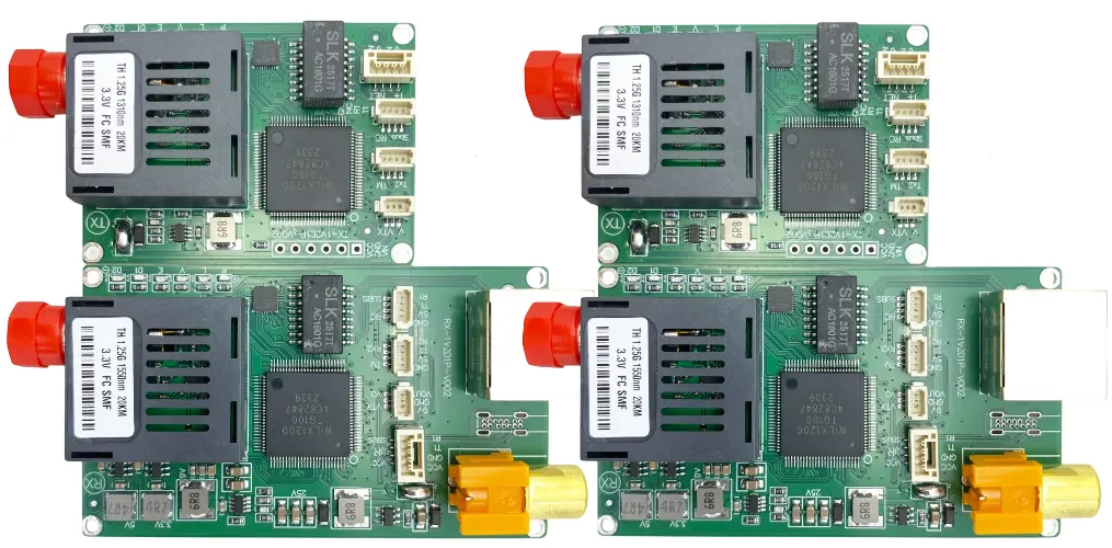
Video and telemetry return through the same fiber via wavelength division multiplexing (WDM). A typical scheme: commands forward on 1310 nm, video return on 1550 nm. The two wavelengths share the same physical fiber strand but are separated at each end by WDM optical couplers (wavelength-selective beamsplitters). This bidirectional-on-one-fiber architecture is critical for fiber-guided platforms because the fiber is being dispensed and cannot be a multi-strand bundle — weight and canister capacity demand a single fiber.
The video pipeline on the airborne board: camera sensor → ISP (image signal processor) → compression engine (H.264 or H.265 hardware encoder) → packetization → optical transmitter. Uncompressed 1080p60 requires ~3 Gbps; after H.264 encoding at a quality level appropriate for surveillance, the same stream can be 10–50 Mbps. Compression is mandatory for any fiber-guided platform with a practical canister because it allows the use of 100 Mbps to 1 Gbps optical interfaces rather than 10 Gbps, with corresponding reductions in transceiver cost, power consumption, and board design complexity.
The video pipeline follows the same physical layer design principles as a dedicated optical data link board, adapted for the dispensed-fiber mechanical environment — in particular, the fiber exit angle and any tension introduced by the dispensing mechanism can cause mode coupling in multimode fiber, so single-mode fiber and wavelength-compatible transceivers are standard practice.
Fiber Dispensing Monitoring
The control board monitors three dispensing parameters, either directly or via the canister interface board:
- Optical power at the receiver: the most fundamental indicator of fiber integrity. Sudden power drop indicates a break; gradual decline may indicate bend radius violations in the dispensed trail or contamination at the exit guide.
- Remaining fiber estimate: derived from velocity integration (∫v dt) compared against calibrated canister capacity. More precise methods use a rotary encoder on the exit spool or a direct fiber length sensor. A low-fiber alert at 10–20% remaining triggers return trajectory calculation.
- Tension at the exit guide: a strain gauge or force sensor on the exit guide detects snagging — the fiber snagging on terrain or an obstacle creates a tension spike before the fiber breaks. Detection gives ~50–200 ms warning, sufficient time to attempt evasive action on some platforms.
All three parameters must be sampled at sufficient rate to support the failsafe logic in Section 6. Optical power sampling at 1 kHz is typical — this provides 1 ms resolution for break detection. Tension sampling at 500 Hz is sufficient. Remaining fiber estimation can run at 10–50 Hz since canister depletion is a slow process relative to the control cycle. The dispensing hardware mechanics are detailed in the fiber dispensing box PCB context.
Failsafe Design for Fiber Loss
The fundamental design requirement: every fiber loss event must have a defined, deterministic response
Unlike a tethered drone where the fiber manages a round-trip and degradation is gradual and predictable, a dispensed fiber can break abruptly with no warning — severed by terrain, a rotor, or an operator error at the ground end. The control PCB must treat fiber loss as an expected event, not an exceptional fault. The response must be pre-defined, implemented in hardware or firmware with watchdog backing, and proven in ground testing before any flight.
Fiber loss detection state machine:
- Optical power falls below threshold T_low (set 3 dB above minimum receiver sensitivity)
- Start timer: 100–500 ms window (distinguishes momentary loss from permanent break; momentary loss can occur during sharp maneuvers that stress the fiber exit angle)
- If power recovers within window: log event, continue operation, alert operator
- If power does not recover: declare fiber break, trigger failsafe mode
Failsafe mode options (pre-configured per mission type):
- Autonomous hover: transition to onboard GPS or barometric hold, loiter at current position, await operator reconnection attempt via RF backup (if equipped)
- Return-to-canister: navigate to the last known canister position using onboard IMU dead reckoning, attempt fiber reconnection
- Terminal maneuver: for munition applications, execute pre-programmed terminal approach to last known target coordinates
- Controlled descent: if autonomous flight is not feasible, throttle down to minimum controlled descent rate and cut motors at ground proximity
The hardware watchdog is mandatory: a dedicated watchdog timer IC (not a software watchdog) monitors the processor’s heartbeat signal. If the processor locks up — due to firmware fault, EMI-induced latch-up, or power glitch — the watchdog asserts the failsafe relay and drives the actuators to a pre-defined safe state within the watchdog timeout (typically 50–200 ms). This is the last line of defense between a processor failure and an uncontrolled platform.
Processor and RTOS Selection
The control PCB requires a processor capable of deterministic real-time execution. The key metrics are worst-case interrupt latency (the delay between an incoming command packet triggering an interrupt and the interrupt service routine beginning execution) and context switch time (the time to save current task state and load a new task). Jitter in these metrics directly adds to the control loop latency budget.
Processor categories:
- ARM Cortex-M7 (e.g., STM32H7): 480 MHz, hardware FPU, worst-case interrupt latency ~12 cycles (~25 ns), sufficient for platforms requiring >5 ms control loop. Cost-effective, widely used in commercial drone flight controllers. Suitable for most fiber-guided surveillance platforms.
- ARM Cortex-R5: lockstep dual-core for safety-critical applications, deterministic response time, no cache latency surprises. Selected for defense platforms where the flight control function requires safety integrity level (SIL) compliance.
- FPGA-based control (Xilinx Zynq, Intel Cyclone): for platforms requiring sub-millisecond control loops, FPGA fabric executes the control algorithm in dedicated logic with deterministic one-clock-cycle latency. The processor (ARM core within the SoC) handles non-real-time functions: telemetry logging, fiber health monitoring, mission management.
RTOS selection: FreeRTOS is the most common choice for embedded drone control due to its small footprint, deterministic task scheduling, and broad ecosystem. Zephyr is gaining adoption for its modern architecture and support for safety certification frameworks. Bare-metal (no RTOS) is acceptable for the simplest platforms where the control loop is the only significant task, but adds complexity as the feature set grows.
Power Architecture for Single-Use Platforms
Expendable fiber-guided platforms face a power architecture constraint that does not apply to reusable drones: the power system must be optimized for a single mission profile (takeoff to end of fiber), with no need for charge cycling management or long-term battery health. This allows aggressive cell selection: high-discharge lithium polymer cells with peak C-rates that would shorten cycle life unacceptably in a reusable platform are entirely appropriate here.
The control PCB’s power distribution must handle the motor startup current surge (several hundred amps in small UAVs) without collapsing the supply voltage below the processor’s brown-out threshold. Bulk capacitance near each ESC’s power input, combined with separate power planes for motor drive and avionics (connected at a single star point), prevents motor-switching noise from coupling into the control electronics.
Battery monitoring: coulomb counting provides state-of-charge for mission management. For expendable platforms, the primary concern is mission completion before discharge, not battery longevity — the state-of-charge curve drives return-to-home or mission abort logic alongside the remaining-fiber estimate. The GPS-denied drone PCB design principles for power distribution in contested environments apply equally here — the absence of GPS jamming concern does not eliminate the need for EMI-hardened power supply design within the avionics bay.
Guided vs. Tethered: Design Differences
| Design Aspect | Fiber-Guided (Dispensed) | Tethered (Spool-Managed) |
|---|---|---|
| Fiber management | Passive dispensing, no retrieval, canister depletes to zero | Active bidirectional spool, motor-controlled tension, fiber retrieved on landing |
| Control loop latency | Sub-50 ms critical for most platforms; <10 ms for fast maneuver types | Higher tolerance — 100–200 ms acceptable for stationary or slow-moving tethered ISR platforms |
| Fiber break response | Must handle abrupt, unwarned breaks; deterministic failsafe mandatory | Can warn before failure; spool motor provides tension feedback predicting break |
| Platform reuse | Often expendable; some ISR variants designed for recovery | Usually reusable; airframe and electronics designed for repeated flights |
| Canister PCB | Passive fiber feed monitoring; no motor drive | Active motor control; tension regulation; bidirectional fiber length tracking |
| EMI hardening | Standard for commercial; MIL-STD-461 for defense | Same requirement range; EMI-resistant design practices apply equally |
Manufacturing and Qualification
The manufacturing approach splits by platform reuse model:
Expendable platforms: Standard FR-4, 4–6 layers, commercial-grade components, automated SMT assembly, 100% in-circuit test (ICT) and functional test, sampled environmental screening. Qualification is by design analysis and limited environmental testing rather than full MIL-STD-810 compliance. Cost is the primary driver — a platform destroyed in a single use cannot carry a $50,000 circuit board. FR-4 PCB fabrication with standard lead-free assembly meets the reliability requirement for a mission profile measured in hours.
Reusable ISR platforms: Approaches military-grade design and qualification — polyimide or high-Tg FR-4 substrate, IPC Class 2 or 3 assembly acceptance, conformal coating for humidity and contamination resistance, MIL-STD-810 environmental qualification testing. Functional testing includes: guidance command loopback at operating temperature extremes, fiber break simulation (optical attenuator inserted to confirm failsafe triggers correctly at the defined threshold), latency measurement across the full command path.
Highleap provides fabrication and assembly for both expendable and reusable fiber-guided control boards, with documentation packages appropriate to each qualification level.
FAQ
How far can a fiber-guided drone fly?
Range is limited by canister capacity — the length of fiber that can be wound into the canister at the airborne end, plus fiber on the ground-side coil. Practical airborne canister capacity is 5–20 km for a canister weighing 2–8 kg. Some larger platforms carry 30+ km. The optical link budget is not the limiting factor — 1310 nm single-mode fiber at 0.35 dB/km with a 20 dB optical budget supports 57 km, far exceeding canister capacity.
Can the fiber-guided architecture support autonomous waypoint navigation?
Yes — autonomous navigation runs on the onboard processor and does not require the fiber link for execution. The fiber link carries operator override commands and returns video for situational awareness. Autonomous modes are particularly important for fiber-guided platforms because the operator may temporarily lose video (due to terrain masking the camera) while the platform continues to navigate autonomously.
What happens if the fiber breaks at the ground end (near the coil)?
The optical loss event is identical from the airborne board’s perspective regardless of where the fiber breaks. The detection and failsafe logic described in Section 6 applies equally to a ground-end break as to an airborne-end break. Physically, a ground-end break may be more common — the fiber near the launch point is stationary and vulnerable to being cut by vehicle traffic or personnel.
How does GPS denial affect this system?
For the fiber communication path: not at all. The fiber link is immune to GPS jamming or spoofing. For the failsafe autonomous mode: significantly. If the failsafe relies on GPS-referenced return-to-home, GPS jamming disables this option. Defense-oriented designs therefore implement IMU-only dead-reckoning failsafe as the primary autonomous mode, with GPS as a secondary option when available. The GPS-denied drone PCB design context addresses the inertial navigation hardware that underpins this capability.

Recommended Posts

Rogers TMM6 PCB Manufacturing for Microwave Filters
Table of contentsWhy Microwave Filter Designers Use...

Taconic fastRise 27 Prepreg PCB Bonding and HDI Fabrication Service
Table of contentsWhat fastRise 27 Is—and What You Are...
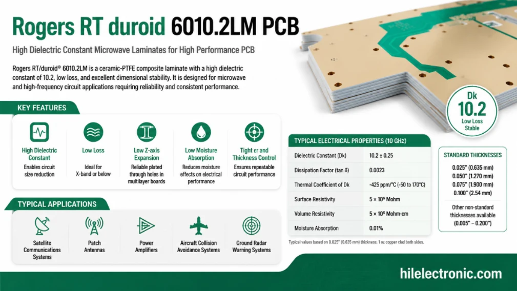
Rogers RT/duroid 6010.2LM PCB Manufacturer and Fabrication Service
Table of contentsIs RT/duroid 6010.2LM the Right Material...
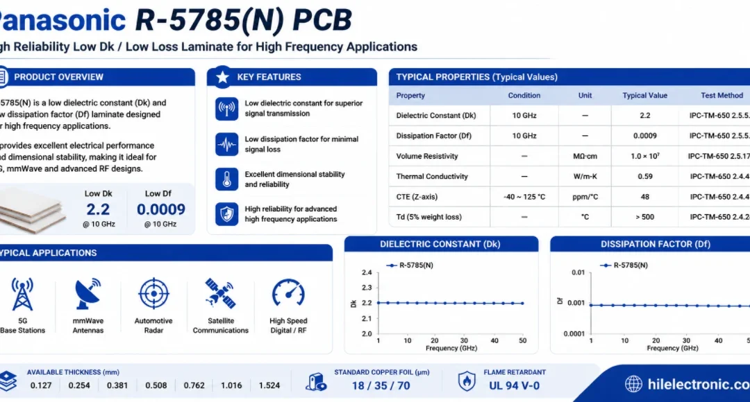
Panasonic R-5785(N) MEGTRON 7 PCB Manufacturer and Fabrication
Table of contentsWhen a Design Should Move to R-5785(N) /...
How to get a quote for PCBs
Let us run DFM/DFA analysis for you and get back to you with a report.
You can upload your files securely through our website.
We require the following information in order to give you a quote:
-
- Gerber, ODB++, or .pcb, spec.
- BOM list if you require assembly
- Quantity
- Turn time