
Fiber Dispensing Box PCB for UAV Fiber Systems

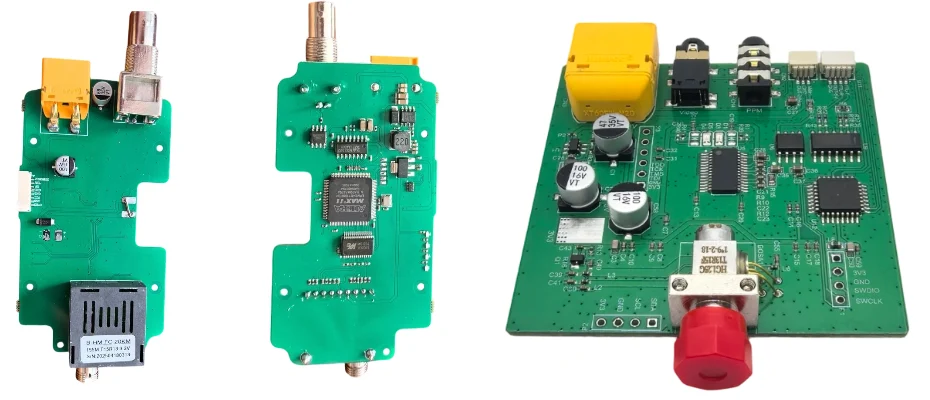
In a fiber-guided or tether-assisted UAV system, the dispensing box is where deployment reliability begins. Before the fiber reaches the aircraft, it has to leave storage cleanly, maintain optical continuity, survive handling, and report its status to the rest of the system. The electronics inside that box determine whether deployment remains controlled, whether faults can be detected early, and whether the ground-side hardware performs predictably under real field conditions.
That is where the fiber-dispensing-box-pcb becomes important. Instead of acting as a simple monitoring board, it often serves as the control layer for payout sensing, environmental tracking, optical continuity supervision, brake or drag management, and system communication. For this type of hardware, PCB design, PCB fabrication, and PCB assembly all matter. Highleap Electronics supports these programs as a PCB manufacturing and PCB assembly factory, helping customers build dispensing box electronics that are easier to prototype, assemble, test, and repeat in production.
Table of Contents
Role of the Fiber Dispensing Box PCB in UAV Systems
A dispensing box PCB sits on the ground-side or launch-side of the fiber deployment path and manages the electronics associated with controlled release, monitoring, and system feedback. In some systems, it is a simple monitor-only board. In others, it becomes a more capable control PCB that supervises braking, payout state, environmental conditions, and communication with other tether-related modules.
The exact role depends on the UAV architecture. Passive dispensing boxes usually focus on status awareness and fault reporting. Active dispensing boxes may add braking, drag regulation, motor control, or tension feedback to shape how the fiber leaves the enclosure. In either case, the board is part of the deployment system, not just a peripheral sensor node.
Typical system responsibilities include:
- Monitoring fiber continuity during payout and standby
- Tracking payout behavior such as exit speed, remaining fiber estimate, or line condition
- Reporting box status to the operator console, ground controller, or tether management subsystem
- Managing braking or release mechanisms in active designs
- Supporting environmental and storage monitoring where long shelf life matters
Because the dispensing box often works as part of a larger tether architecture, its electronics may connect naturally with ground-side canister control boards or with downstream fiber pay-out spool electronics depending on how the deployment path is split across the system.
Sensing, Control, and Optical Monitoring Functions
The most practical way to understand a fiber-dispensing-box-pcb is to look at what it measures and what it controls. In passive designs, the board usually focuses on health visibility. In active designs, it closes the loop around payout behavior. Either way, the quality of the electronics determines how well the system can detect abnormal deployment before a line failure becomes a mission failure.
Common sensing and monitoring functions include:
- Optical continuity monitoring to detect fiber break, major attenuation, or signal loss
- Payout speed feedback from encoder-based or sensor-based measurement
- Remaining fiber estimation through depletion models, weight sensing, or spool-state logic
- Tension or drag observation in systems that regulate line behavior
- Temperature and humidity logging for storage condition awareness
- Fault signaling for jam, break, abnormal payout, or deployment interruption
In active variants, the PCB may also control a brake, magnetic drag element, small actuator, or resistive motor stage. This introduces a higher level of board complexity because sensing and actuation must coexist on one layout without letting power-stage activity disturb low-level monitoring channels. That mixed-domain requirement is one reason these boards often benefit from design practices similar to anti-interference PCB design for UAV electronics, especially when analog sensing, communication, and drive circuitry share limited space.
For dispensing systems used in broader optical UAV platforms, the sensing layer may also interact with fiber-optic tether electronics in UAV systems so that payout status, communication state, and link health stay coordinated rather than isolated.
PCB Design Priorities for Dispensing Box Electronics
Compared with a generic low-speed control board, a fiber dispensing box PCB usually has more demanding physical and electrical design priorities. It may look simple at the schematic level, but the board still needs to handle rugged connectors, mixed sensor inputs, noisy actuators, long storage requirements, and field-facing interfaces. That makes PCB design discipline a major part of product reliability.
Important PCB-level design priorities often include:
- Power-domain separation between sensing circuits, MCU logic, communication interfaces, and any brake or actuator driver
- Stable regulator design for low-noise sensor supply and robust field operation
- Connector strategy for locking field connectors, service connectors, and sealed I/O paths
- Grounding and EMC control to prevent actuator switching noise from corrupting monitoring signals
- Mechanical reinforcement for boards exposed to cable force, enclosure stress, or transport vibration
- Test access planning for production validation, depot checks, and field maintenance
Board structure also matters. Many dispensing box products can be built on standard 4-layer FR-4, but not all should be. If the design combines stronger power handling, high-noise actuation, optical monitoring, and ruggedized interfaces, stackup choice and copper strategy become part of the engineering decision rather than a default manufacturing setting.
For programs that also involve custom UAV controller boards, payload boards, or tether-related electronics, this work often sits alongside broader custom drone PCB development rather than as a standalone accessory board project.
Reliability for Storage, Transport, and First Deployment
One of the most overlooked challenges in fiber dispensing hardware is that the board may spend far more time in storage or transport than in active operation. That changes the reliability problem. Instead of optimizing only for runtime behavior, the design also has to survive environmental exposure, shelf life, handling, and first-use readiness after extended idle periods.
For this reason, a well-designed dispensing box PCB often includes measures such as:
- Conformal coating or selective protection against humidity, dust, and contamination
- Preference for storage-stable components where long shelf intervals are expected
- Self-test or health-check modes that can verify board readiness before deployment
- Environmental logging for temperature, humidity, and storage history
- Connector and enclosure compatibility for repeated handling and transport shock
Reliability is not only about component choice. It also depends on the relationship between enclosure mechanics, PCB mounting, connector loading, and fault behavior during first payout. A board that passes bench test can still fail in deployment if the mechanical path into the PCB is not well managed. This is why storage-ready and field-ready dispensing hardware must be engineered as a whole assembly, not only as a schematic.
In harsher environments, EMI behavior and contamination resistance may matter at the same time. That is one reason rugged deployment hardware sometimes overlaps with manufacturing practices used in EMI-resistant drone electronics, especially where enclosure density and mixed-domain circuitry are involved.
PCB Fabrication and Assembly for Fiber Dispensing Hardware
From a manufacturing perspective, fiber dispensing box PCBs are more specialized than they first appear. They often combine low-power logic, sensor interfaces, rugged field I/O, optional motor or brake drive stages, and deployment-related diagnostics on one assembly. That means both bare board quality and assembly execution directly affect product performance.
From the fabrication side, the board may require:
- Multilayer PCB construction for cleaner routing and domain separation
- Controlled copper strategy where power sections and sensing sections coexist
- Milled features or slots for isolation, mounting, or connector accommodation
- Mechanical accuracy for alignment with housings, guides, and rugged connectors
- Material selection based on environment and service conditions rather than cost alone
From the assembly side, important considerations include SMT and through-hole integration, connector anchoring, coating sequence, calibration flow, and functional test coverage. When the product includes both monitoring and actuation, inspection strategy becomes especially important because errors in assembly may not show up until the system is under payout load.
For projects that require sourcing, board fabrication, assembly, and production planning in one flow, Highleap also supports turnkey PCB assembly. As a manufacturer with in-house PCB assembly capability and broader electronic manufacturing service support, Highleap Electronics can help move fiber dispensing box PCB designs from engineering samples into repeatable production hardware.
FAQ
What is a fiber-dispensing-box-pcb?
It is the control and monitoring board used inside a fiber dispensing box, deployment unit, or related ground-side fiber handling system for UAV applications.
Is a dispensing box PCB always passive?
No. Some designs are monitor-only, while others include active braking, drag regulation, or deployment-related actuation.
Why does PCB design matter for a dispensing box?
Because sensor reliability, connector durability, power behavior, EMI control, and first-use readiness all depend on how the board is designed, fabricated, and assembled.
Can this type of board be built on standard FR-4?
Yes, in many cases. But the right stackup, copper strategy, and board structure still depend on the power level, interface density, and environmental requirements of the product.
Can Highleap Electronics support both prototypes and production for this type of PCB?
Yes. Highleap supports PCB fabrication, PCB assembly, turnkey assembly, and broader EMS workflows for custom UAV and fiber-related electronics projects.

Recommended Posts
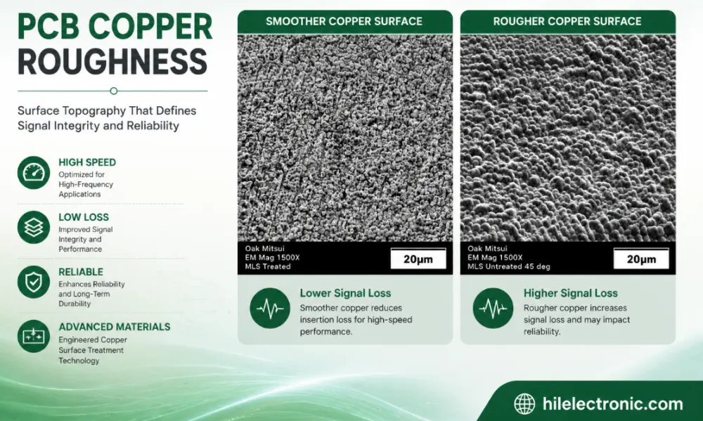
PCB Copper Roughness: Signal Loss, Material Selection and Manufacturing Control
Table of contentsWhat Is PCB Copper Roughness?How Copper...
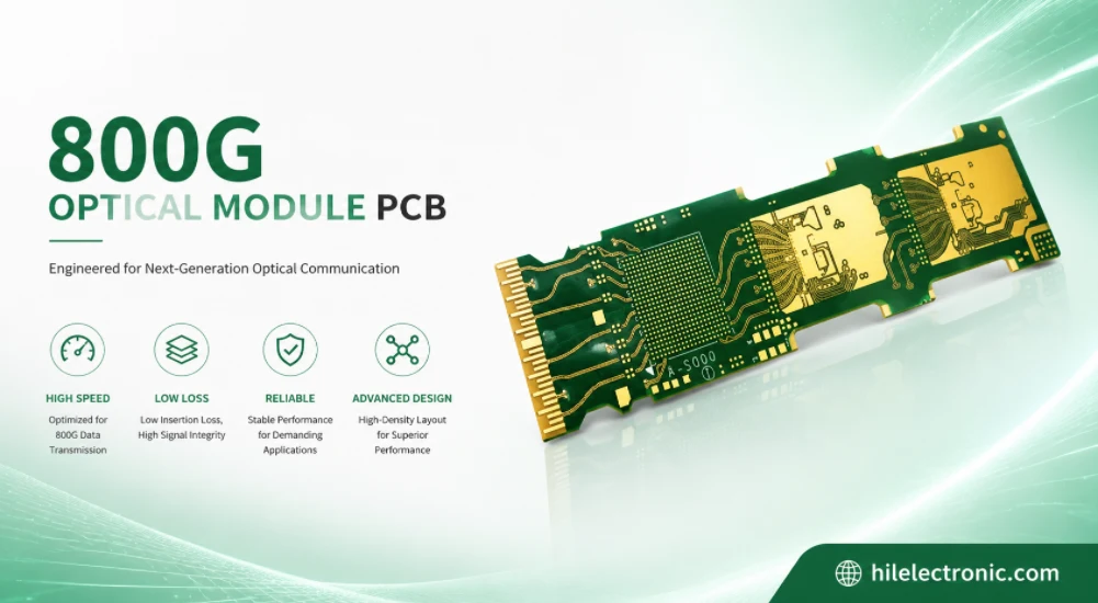
800G Optical Module PCB Manufacturing and Assembly Service
Table of contentsWhat Makes an 800G Optical Module PCB...
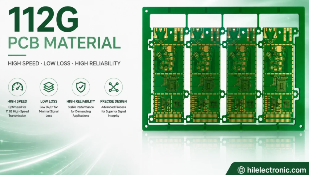
112G PCB Material Selection and High-Speed PCB Manufacturing
Table of contentsWhat “112G PCB Material” Actually...
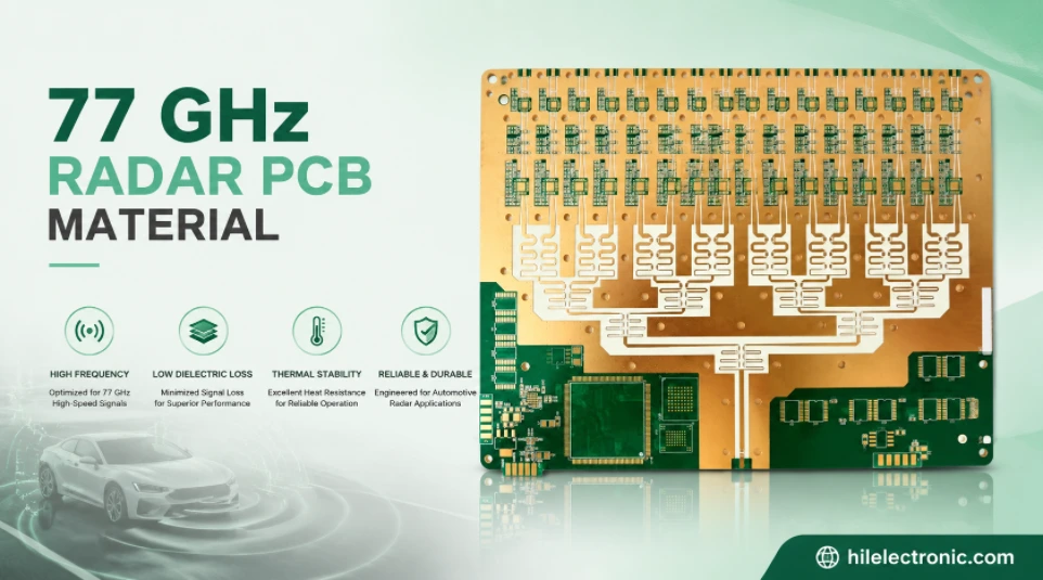
77 GHz Radar PCB Material Selection and Manufacturing Guide
Table of contentsWhat 77 GHz Changes in a PCBCommon 77 GHz...
How to get a quote for PCBs
Let us run DFM/DFA analysis for you and get back to you with a report.
You can upload your files securely through our website.
We require the following information in order to give you a quote:
-
- Gerber, ODB++, or .pcb, spec.
- BOM list if you require assembly
- Quantity
- Turn time