
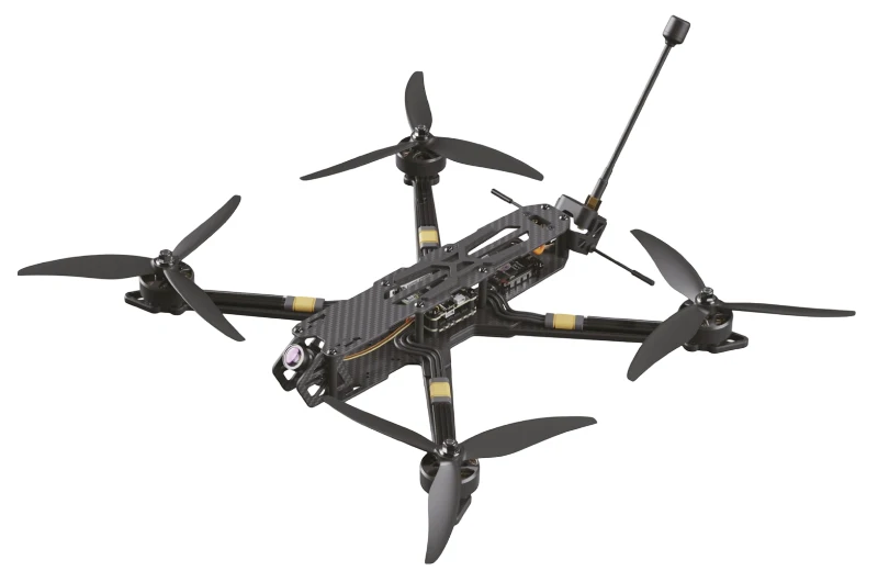
Defense-Grade Military Fiber Drone PCB Manufacturing

Military UAV programs set the requirements ceiling for fiber optic drone PCB design. The boards must survive environments that commercial designs never encounter: −55 °C to +125 °C operating range, vibration to 20 g across a 20–2000 Hz sweep, 40 g shock from launch, salt fog, fungus exposure, sand and dust ingestion, and altitude from sea level to above 15,000 m. They must maintain secure, undetectable communication in electromagnetic environments designed to defeat radio-based links. And they must do all of this with the supply chain discipline, documentation traceability, and inspection rigor that defense procurement requires.
Understanding what military standards actually require — as opposed to what invoking them is sometimes assumed to mean — is essential for any engineer designing toward this application. The standards are specific about test methods, acceptance criteria, and documentation. Meeting them is not optional for programs with defense contracts; approximating them is not equivalent.
Get a Military Fiber Drone PCB Quote
Quick answer
A military fiber drone PCB meets IPC Class 3, MIL-STD-810 (environmental), and MIL-STD-461 (EMC) standards while providing secure, jam-proof optical data links with zero RF emission. The design combines fiber optic drone PCB signal integrity requirements with defense-grade materials, manufacturing processes, inspection protocols, and supply chain controls. The result is a board that performs predictably through the full operational life of the platform, in environments that would quickly degrade commercial-grade assemblies.
Table of Contents
- Why Military UAVs Select Fiber Over Hardened RF
- Applicable Standards: What Each Actually Requires
- Materials: Substrate, Copper, and Surface Finish
- Manufacturing Process Controls
- Conformal Coating and Encapsulation
- Loitering Munition Application
- Tactical ISR Platform Application
- Secure Boot and Anti-Tamper Design
- Supply Chain and Counterfeit Prevention
- Environmental Qualification Testing
- FAQ
Why Military UAVs Select Fiber Over Hardened RF
Low Probability of Detection (LPD)
Every RF link — encrypted, spread-spectrum, frequency-hopping — emits electromagnetic energy that can be detected, localized, and targeted by modern electronic warfare systems. Fiber emits nothing. A fiber-tethered drone operating in contested airspace produces zero RF signature from its communication link. For ISR missions where detection terminates the mission and may terminate the operator, zero emission is the only acceptable communication model.
Low Probability of Intercept (LPI)
Even fully encrypted RF transmissions can be captured for later cryptanalysis, traffic analysis, or direction finding. Optical fiber physically confines the signal — the only way to intercept a fiber communication is to physically access the fiber, which requires detecting and reaching it, and which can be detected by optical time-domain reflectometry (OTDR) measurements that reveal the tap as a power loss event.
Absolute Jam Immunity
The anti-jamming drone PCB addresses RF spectrum hardening — spread spectrum, frequency agility, nulling antennas. These techniques increase the power required to jam, but a sufficiently powerful jammer in proximity wins eventually. Fiber eliminates this attack surface entirely: no RF signal means no RF jamming is possible, regardless of the jammer’s power or sophistication. Fiber-guided and fiber-tethered systems are selected specifically when the operational environment makes RF link survival uncertain.
The bandwidth advantage of fiber is an additional motivation for some programs: single-mode fiber at 1310 nm carries 10 Gbps on a strand weighing 5 g/m, compared to the complexity and weight of RF systems achieving even 1 Gbps over line-of-sight links. For platforms carrying multiple EO/IR cameras plus SAR or SIGINT payloads, fiber’s bandwidth enables sensor fusion at the ground station that RF links cannot support.
Applicable Standards: What Each Actually Requires
| Standard | Scope | Key Requirements vs. Commercial Class 2 |
|---|---|---|
| IPC-6012 Class 3/3A | Rigid PCB fabrication qualification | Annular ring minimum 50 µm (vs 25 µm Class 2); plated hole wall thickness 25 µm minimum; tighter impedance tolerance; all coupons tested and documented |
| IPC-A-610 Class 3 | Assembly workmanship acceptance | Side overhang on gull-wing leads ≤25% lead width (vs 50% Class 2); no cold solder joints; no head-in-pillow on BGA; every assembly inspected not sampled |
| MIL-PRF-31032 | PCB performance specification | Thermal shock cycling (−65 to +125 °C, 100 cycles), moisture resistance, dielectric withstanding voltage, conductor resistance; coupon testing per production lot |
| MIL-STD-810H | Environmental engineering — test methods | Method 501.7 (high temp), 502.7 (low temp), 514.8 (vibration), 516.8 (shock), 507.6 (humidity), 510.7 (sand/dust), 520.4 (temperature-humidity-vibration-altitude combined) |
| MIL-STD-461G | EMC — emissions and susceptibility | CE101/102 (conducted emissions), RE101/102 (radiated emissions), CS101/114/115/116 (conducted susceptibility), RS101/103 (radiated susceptibility) |
| MIL-STD-464C | Electromagnetic environmental effects at system level | Lightning indirect effects, EMP hardening, HIRF (high-intensity radiated fields) — typically 200 V/m at 2–18 GHz |
IPC Class 3A (the “A” suffix for space and military applications) adds requirements beyond Class 3: minimum 1 oz (35 µm) copper on all layers including inner layers, microsectioning of coupons from every production panel, and additional documentation that traces each board to its production lot.
Materials: Substrate, Copper, and Surface Finish
Standard FR-4 (Tg 130–140 °C) is inadequate for the −55 to +125 °C operating range required by MIL-STD-810. The substrate’s glass transition temperature must exceed the maximum operating temperature with margin — high-Tg FR-4 (Tg 170–175 °C, per Isola 370HR specification) is the minimum for most defense applications. Polyimide substrate (Tg 250 °C+) is selected when the thermal range is extreme or when the program requires compliance with MIL-PRF-31032 Group A testing that includes thermal cycling to −65 °C.
Copper weight: IPC Class 3 requires 1 oz (35 µm) minimum on outer layers. Inner layers should match for thermal uniformity and to avoid differential CTE stress during temperature cycling. Heavy copper (2 oz or 3 oz) is used for power distribution traces in motor controller sections and for thermal spreading beneath high-dissipation components.
Surface finish: Electroless Nickel Immersion Gold (ENIG) per IPC-4552 is standard — 3–6 µin gold over 120–240 µin nickel. The gold protects the nickel from oxidation during storage; the nickel provides the soldering surface. ENIG is compatible with both lead-free and tin-lead soldering (tin-lead is still permitted for Class 3 military applications where the DoD has granted exemption from RoHS). Hard gold (electrolytic, 30+ µin) is used on edge connectors subject to repeated insertion. Immersion silver is avoided for long-term storage applications due to silver migration risk in humid environments.
For the signal integrity requirements of 10 Gbps optical data link sections, low-loss materials (Megtron 6, Isola I-Tera MT40) reduce insertion loss on long serial runs. The military thermal requirements and the signal integrity requirements impose a combined material specification that eliminates standard FR-4 and points toward the high-Tg, low-loss laminate category.
Manufacturing Process Controls
IPC Class 3 manufacturing requires documented process control at every step. The fabricator must demonstrate process capability (Cpk) for hole registration, plated through-hole wall thickness, impedance, and surface finish thickness. First article inspection (FAI) per AS9102 verifies that the first production board conforms to design intent before lot release.
Solder paste inspection (SPI) after printing, automated optical inspection (AOI) after reflow, and X-ray inspection of all BGA and bottom-terminated components are mandatory, not optional. AOI algorithms must be tuned to the specific board — false calls are not acceptable because they generate manual inspection overhead that creates its own quality risks. X-ray must be performed by trained operators using calibrated equipment; image interpretation for head-in-pillow (HiP) and non-wet open (NWO) defects requires experience that casual X-ray inspection does not provide.
Microsectioning: production coupons from each panel are cross-sectioned, polished, and examined under magnification. Plated hole wall thickness, knee coverage, dielectric thickness, and registration are measured and documented. Any coupon failing the IPC Class 3 acceptance criteria causes the entire panel to be quarantined pending disposition.
Highleap’s IPC standard compliance and quality assurance processes support Class 3 production with full documentation packages.
Conformal Coating and Encapsulation
Conformal coating is mandatory for military boards operating in humidity, salt fog, and condensation environments. The coating encapsulates the solder joints and component bodies, preventing moisture ingress, contamination, and ionic surface leakage that could cause intermittent failures.
Coating types for defense applications:
- Acrylic (AR): easiest to rework, good moisture resistance, limited chemical resistance. Suitable for boards in enclosed housings.
- Polyurethane (UR): better chemical resistance than acrylic, moderate rework difficulty. Common choice for general military applications.
- Silicone (SR): widest temperature range (−65 to +200 °C), flexible, excellent vibration resistance. Required for the most demanding thermal environments. Rework is difficult — requires solvent cleaning that can attack nearby materials.
- Parylene (XY): vapor-deposited, pinhole-free, thin (12–50 µm), excellent coverage of complex geometries. Not reworkable without specialized equipment. Selected for boards where rework is never expected or acceptable.
Coating application must mask connectors, test points, and components with thermal interfaces. Masking quality affects reliability: masked areas that contaminate connector contacts cause intermittent connections; over-masked areas leave unprotected board surface. For conformal-coated assemblies, IPC-A-610 Class 3 acceptance criteria require uniform coverage with no bubbles, delamination, or runs that could trap moisture.
Loitering Munition Application
Loitering munitions (LMs) represent the fiber-guided side of the military UAV family: expendable platforms that fly a mission and are not recovered. PCB requirements for LMs differ from reusable ISR drones in several ways that affect design and manufacturing decisions.
Single-mission reliability model: the board must function correctly for the mission duration (typically 30–120 minutes) with no failures. It does not need to survive multiple missions or pass life testing at 1000+ hours. This shifts the qualification strategy from life testing to mission reliability testing: environmental screening at 100% of units, functional test before and after screening, and burn-in at elevated temperature (typically 48–72 hours at 85 °C) to eliminate early-life failures before fielding.
Storage survivability: LMs may be stored for years before use. The PCB must survive the storage environment (temperature cycling in sealed containers, humidity fluctuations, occasional shock from handling) and then perform correctly on the first power-up after storage. Components with limited shelf life (electrolytic capacitors, batteries) require attention to storage condition management and periodic replacement.
The guidance PCB for loitering munitions is detailed in the fiber-guided UAV control PCB context, which covers the command latency, failsafe, and dispensing monitoring requirements specific to expendable platforms.

Tactical ISR Platform Application
Reusable tactical ISR platforms represent the most demanding end of the military fiber drone PCB design space: the boards must survive hundreds of flight hours across the environmental range, maintain performance as components age, and support scheduled maintenance including firmware updates and diagnostics.
Design life: 500–2000 flight hours is typical for defense ISR platforms. The PCB must be designed and qualified to this life figure with appropriate derating. Key life-limiting mechanisms: solder joint fatigue from thermal cycling (each flight is a thermal cycle), connector wear from repeated mating, capacitor aging (electrolytic capacitance decreases over time, increasing ripple voltage in power supplies), and optical transceiver laser aging (threshold current and slope efficiency drift with operating hours).
The tether infrastructure for reusable platforms — spool PCB, ground station canister electronics, and optical data link board — must match the communication board’s reliability class. A Class 3 communication board connected to a Class 2 spool board creates a weak link at the spool that undermines the investment in the communication board.
Onboard diagnostics: reusable military platforms benefit from built-in test (BIT) capability — self-test routines that execute on power-up and continuously during operation, reporting system health to maintenance crews. BIT data drives predictive maintenance scheduling, enabling component replacement before failure rather than after. The optical DDM data from the transceiver (transmit power, receive power, laser bias) is a primary BIT input — trends in these parameters predict fiber and transceiver health months before failure.
Secure Boot and Anti-Tamper Design
Defense programs handling classified mission data or operating algorithms require protection against unauthorized firmware modification, data extraction, and reverse engineering. The PCB design implements multiple layers of protection:
Secure element: A dedicated hardware security module (HSM) or trusted platform module (TPM) stores cryptographic keys in tamper-evident non-volatile memory. Keys are generated on-device and never transmitted in plaintext. The secure element performs authentication operations and key derivation without exposing key material to the main processor’s memory space.
Authenticated boot chain: The boot ROM (in mask ROM, unmodifiable) verifies the first-stage bootloader signature using the public key stored in the secure element. The first-stage bootloader verifies the second-stage; the second-stage verifies the application firmware. Any break in the chain halts boot and triggers a tamper response. This prevents an attacker who can modify flash memory from executing unauthorized code.
Zeroization on tamper detection: Physical tamper sensors (accelerometer for drop/impact detection, light sensor for case opening, voltage monitor for supply manipulation) connect to the secure element’s tamper input. On tamper event, the secure element overwrites cryptographic keys with zeros — the operation completes in microseconds, faster than any practical key extraction attack.
Anti-tamper mesh: Fine conductive traces routed on inner PCB layers in a pattern that encloses sensitive components. Any drilling or delamination attempting to access the components beneath the mesh breaks the trace, detected as a continuity failure that triggers zeroization. The mesh pattern must be routed to prevent reconstruction from layer-by-layer delamination.
Protective coatings: Epoxy potting or high-hardness conformal coating over sensitive component areas makes physical access by grinding or polishing more difficult and more destructive — any attack that successfully reaches the silicon damages the components being attacked.

Supply Chain and Counterfeit Prevention
Counterfeit electronic components are a documented threat to defense programs — upscreened commercial parts relabeled as military grade, reclaimed components from salvage boards, and outright fabricated parts have all been found in defense supply chains. The consequences range from premature field failures to deliberate hardware trojans in adversary-manufactured components.
SAE AS6171 provides the test methods for suspect/counterfeit component detection. Key methods: X-ray fluorescence (XRF) to verify lead frame alloy composition, scanning electron microscopy (SEM) for surface markings and die topology, electrical characterization against original datasheet limits, and decapsulation for visual die inspection. Not every component on every board requires this level of screening — risk-based screening focuses on high-density ICs, military-grade-marked parts, and components sourced outside the franchised distributor network.
DFARS (Defense Federal Acquisition Regulation Supplement) compliance: US defense contractors must source electronic components only from original equipment manufacturers (OEMs), authorized distributors, or independent distributors who comply with AS6081 anti-counterfeiting requirements. DFARS 252.246-7008 makes this a contract requirement, not a recommendation.
Component traceability: every component on a defense board should be traceable to its date code, lot number, and source. This enables targeted recall and inspection if a counterfeit lot is identified in the supply chain after boards are fielded. Traceability data is captured at assembly and stored in a configuration management system tied to each board’s serial number.
Environmental Qualification Testing
MIL-STD-810H test methods relevant to airborne fiber drone PCBs:
Method 501.7 (High Temperature): Operational test at +71 °C (aircraft upper limit), storage test at +85 °C. The optical transceiver must meet its BER specification at temperature extremes — laser threshold current and slope efficiency are temperature-dependent, and the board’s power supply must compensate.
Method 502.7 (Low Temperature): Operational at −40 °C, storage at −55 °C. Cold start requires attention: electrolytic capacitors have elevated ESR at low temperature; crystal oscillators may not start reliably below −40 °C without heater elements; conformal coatings may crack if applied too thickly.
Method 514.8 (Vibration): Random vibration profile appropriate to the platform’s operational environment. For UAVs, the relevant profile includes propulsion-induced vibration (rotor harmonics, motor vibration) and turbulence. Solder joint reliability is the primary concern — BGA and QFP packages under vibration fatigue — requiring adequate underfill for large BGAs and appropriate footprint design to distribute vibration stress.
Method 516.8 (Shock): Half-sine shock pulses at 40 g, 11 ms duration (functional shock), and 75 g sawtooth (crash hazard). Connectors, crystals, and inductors are the most vulnerable components to shock. Board mounting standoff spacing must be designed to avoid resonance at shock pulse frequencies.
Qualification testing is conducted on engineering development units (EDUs) before design release. Production lots are verified by acceptance testing of samples per the contract’s inspection level (typically S-2 per MIL-STD-1916 or equivalent).
FAQ
Does every military drone require fiber communication?
No. Many military drones operate with hardened RF links — frequency-hopping, spread-spectrum, jam-resistant waveforms. Fiber is selected for specific operational requirements: zero RF emission for LPD/LPI, absolute jam immunity, or bandwidth exceeding practical RF capability. The decision is made by the platform’s communication requirements document, not by a general preference for fiber over RF.
Can commercial fiber drone boards be adapted for military use?
Commercial boards can serve as proof-of-concept for prototyping and concept validation. They cannot substitute for military-grade designs in production programs. The differences are not cosmetic — material Tg, copper thickness, via plating, assembly workmanship, component screening, and documentation traceability are all materially different between commercial and military-grade production. Attempting to pass commercial boards through military qualification testing typically results in failure at environmental screening.
What is the lead time for military-grade PCB fabrication?
IPC Class 3 fabrication with MIL-PRF-31032 compliance typically requires 4–8 weeks, compared to 1–2 weeks for commercial Class 2. The additional time reflects coupon testing, microsectioning, and documentation preparation that are not performed in commercial production. Programs with aggressive timelines should plan for this lead time from the start of fabrication release, not from contract award.
How does Highleap support defense programs?
Highleap provides defense-grade fabrication with IPC Class 3 process controls and assembly to IPC-A-610 Class 3 standards. Full traceability documentation, controlled impedance with TDR verification, conformal coating, and component sourcing support are available. Our military PCB capabilities cover the fabrication and assembly requirements described in this article.

Recommended Posts

Rogers TMM6 PCB Manufacturing for Microwave Filters
Table of contentsWhy Microwave Filter Designers Use...

Taconic fastRise 27 Prepreg PCB Bonding and HDI Fabrication Service
Table of contentsWhat fastRise 27 Is—and What You Are...
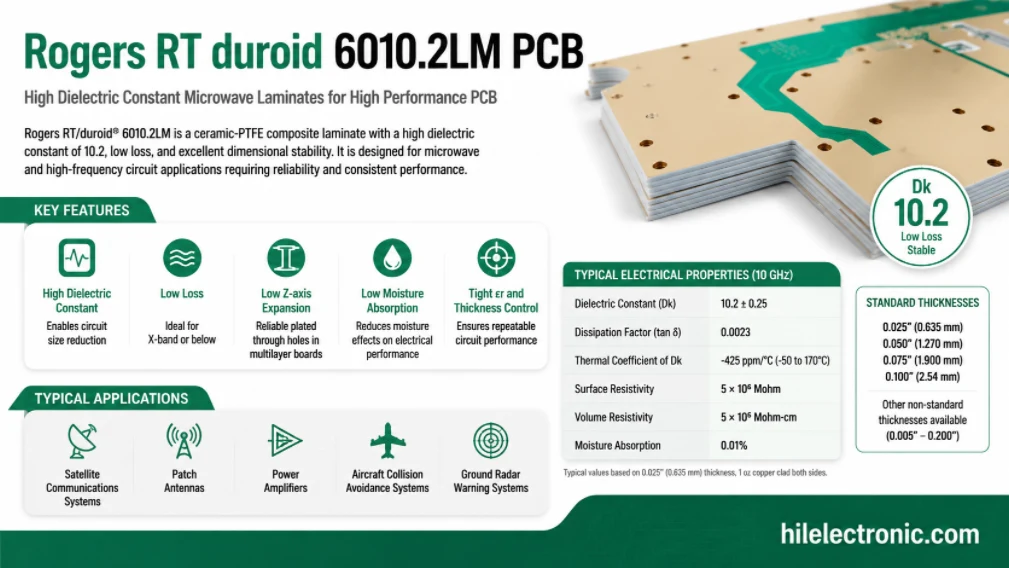
Rogers RT/duroid 6010.2LM PCB Manufacturer and Fabrication Service
Table of contentsIs RT/duroid 6010.2LM the Right Material...
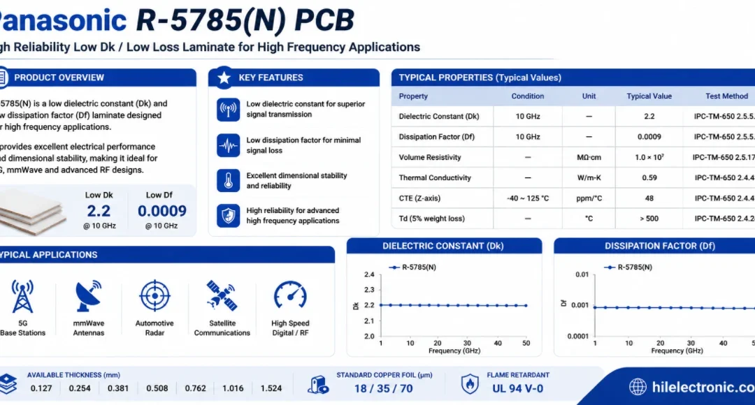
Panasonic R-5785(N) MEGTRON 7 PCB Manufacturer and Fabrication
Table of contentsWhen a Design Should Move to R-5785(N) /...
How to get a quote for PCBs
Let us run DFM/DFA analysis for you and get back to you with a report.
You can upload your files securely through our website.
We require the following information in order to give you a quote:
-
- Gerber, ODB++, or .pcb, spec.
- BOM list if you require assembly
- Quantity
- Turn time