
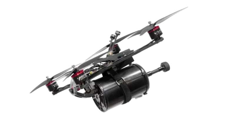
Fiber Optic Drone PCB for UAV Manufacturers and Fiber-Guided Drone Systems

Fiber optic drone PCB refers to the circuit-board architecture used in unmanned systems that communicate through optical fiber rather than relying only on conventional radio links. In these designs, electrical data is converted at an optical interface, transmitted through fiber, and recovered at the receiving end. The practical advantages are higher link-bandwidth potential, strong immunity to electromagnetic interference along the fiber path, and no intentional RF emission from the optical link itself. These properties make fiber-based UAV communication relevant in tethered drones, fiber-guided platforms, and high-security unmanned systems where radio-based communication becomes vulnerable or limiting. Fiber itself is widely used when high bandwidth and immunity to electromagnetic interference are required.
Get a Fiber Optic Drone PCB Quote
Quick answer
Fiber optic drone PCBs are used in UAV systems that need an optical communication path instead of, or in addition to, a standard wireless RF link. Typical design priorities include electro-optical transceiver integration, controlled-impedance high-speed routing, fiber connector and strain-relief design, power isolation, and environmental hardening for airborne operation. Common implementation classes include 1 Gbps and 10 Gbps optical links built around standard SFP or SFP+ transceivers.
Table of Contents
- Why Fiber Optics Is Used in Certain Drone Systems
- Core Architecture of a Fiber Optic Drone PCB
- Fiber Optic Drone PCB by Application Type
- PCB Stack, Signal Integrity, and Optical Interfaces
- Manufacturing and Assembly Requirements
- Subsystem Map and Related PCB Types
- Starting a Fiber Optic Drone PCB Project
- Fiber Optic Drone PCB FAQ
Why Fiber Optics Is Used in Certain Drone Systems
Fiber optic communication is not a universal replacement for drone radio. It is used where the communication path must tolerate severe electromagnetic interference, where radio detection or jamming is a concern, or where a physical tether is already part of the system architecture. Optical fiber is inherently immune to electromagnetic interference in a way copper conductors and wireless links are not, which is one reason fiber-guided and tethered optical UAV concepts have appeared in contested and high-interference environments. Recent reporting on fiber-guided UAVs in Ukraine also highlights reduced vulnerability to electronic warfare compared with radio-guided drones.
Higher practical bandwidth headroom
The advantage of fiber is not that it removes all bandwidth limits, but that it shifts the bottleneck away from the wireless channel. A fiber link can carry multi-gigabit traffic using standard optical transceiver classes such as 1G SFP and 10G SFP+, which are established industry formats. In UAV applications that combine video, telemetry, and control data, this gives far more headroom than a conventional radio link of similar size and weight typically provides.
Resistance to EMI and jamming
The fiber medium itself does not pick up electromagnetic noise the way electrical cabling does, and it does not radiate a radio signal along the communication path. That makes it attractive for UAV systems operating near jammers, radar, power infrastructure, or in dense RF environments. This is also why optical communication is relevant to interference-resistant drone circuit boards, especially when the design goal is to reduce dependency on vulnerable wireless links.
Lower detectability of the communication path
A radio link intentionally radiates energy and can be detected or direction-found. An optical fiber link does not radiate RF energy along the communication path itself. That does not make the entire drone “undetectable,” but it does reduce exposure associated with the communications channel. In defense-oriented platforms, this property overlaps with the design logic behind defense-grade UAV fiber board applications.
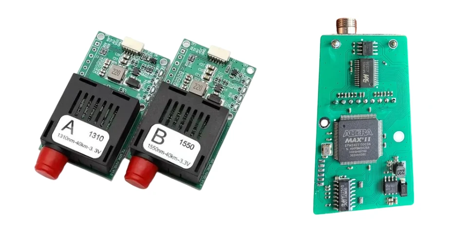
Core Architecture of a Fiber Optic Drone PCB
A fiber optic drone PCB is not just an ordinary flight or video board with an optical module attached. The architecture changes in four important areas: the electro-optical interface, the fiber management interface, power-domain separation, and environmental hardening. Those four areas define whether the board can actually function in a drone or missile-style optical-link system rather than only on a bench. Standard optical modules also impose known electrical-interface requirements through their pluggable connector format.
| Subsystem | Role on the board | Key design concern |
|---|---|---|
| Electro-optical transceiver interface | Converts between high-speed electrical data and optical transmission | Controlled-impedance differential routing and power integrity |
| Fiber management interface | Connects to spool, tether, or dispensing hardware | Strain relief, alignment, vibration tolerance, connector retention |
| Power-domain separation | Keeps the optical interface isolated from motor and switching noise | Dedicated regulation, filtering, and return-path control |
| Environmental hardening | Protects the board and optical interfaces in airborne use | Conformal coating, masking, mechanical retention, and vibration resistance |
The optical transceiver host function connects closely with optical data link board design, while spool and canister electronics often deserve their own dedicated board design because their mechanical and connector requirements differ from those of the airborne data board.
Fiber Optic Drone PCB by Application Type
Not all optical UAV systems are the same. Some are tethered drones with a managed fiber link to the ground. Others are fiber-guided unmanned platforms that dispense fiber during flight. Others still use optical links inside a larger secure or hardened UAV architecture. Treating them as one product type leads to bad PCB assumptions, because the board-level priorities differ between the airborne node, the spool assembly, and the ground-side electronics. Patents and current defense reporting both show that optical-fiber UAV concepts can involve tethered architectures as well as guided, dispensed-fiber control architectures.
| Application | Key PCB function | Typical optical role |
|---|---|---|
| Tethered surveillance drone | Video, telemetry, and tether-side interface control | Managed fiber tether to a ground station or support node |
| Fiber-guided UAV or munition | Guidance command processing and optical uplink/downlink handling | Passively dispensed optical-fiber control link |
| Military ISR platform | Secure communication and a hardened optical interface | Protected optical channel inside a defense UAV architecture |
| Industrial inspection drone | Real-time video and tether-side data transmission | Optical tether in EMI-sensitive or high-data-rate environments |
PCB Stack, Signal Integrity, and Optical Interfaces
The board-level challenge in a fiber optic drone PCB is not “routing light on the PCB.” The fiber carries light, but the board still has to route high-speed electrical signals cleanly between the processor, FPGA, serializer, camera interface, and optical transceiver. Once the board uses 1G or 10G optical modules, the electrical side becomes a signal-integrity problem involving controlled-impedance differential pairs, good reference planes, clean power delivery, and minimized discontinuities. SFP and SFP+ modules are standardized around 1G and 10G classes respectively, so those are realistic anchor points for UAV optical-link board design.
A multilayer stack is typically required when the board combines an optical transceiver host interface, processor logic, motor-related subsystems, and environmental hardening in one compact assembly. The exact layer count depends on data rate, form factor, connector density, and isolation needs; it should not be written as one fixed minimum for every project. What matters more is that high-speed differential routing has continuous reference planes, controlled return paths, and clean separation from noisy power electronics.
Where the optical interface shares board space with dense digital logic, HDI features and careful via strategy may be required. If the design also includes substrate-through interconnect or very compact package transitions, the signal-integrity work can overlap with glass interposer or vertical-interconnect design logic, although that depends on the platform architecture rather than being a universal requirement.
Manufacturing and Assembly Requirements
Fiber optic drone PCBs are manufactured and assembled more like mixed high-speed communication hardware than ordinary hobby-drone boards. The fabrication flow often requires controlled-impedance verification, tighter attention to differential-pair geometry, and better control over stack-up consistency than standard commercial UAV boards. If the board carries a pluggable optical module or dense optical connector hardware, assembly accuracy becomes just as important as fabrication quality.
Controlled impedance and high-speed routing
The electrical paths between the processor and the optical interface must be fabricated as verified high-speed channels, not just ordinary digital traces. That usually means controlled differential impedance, consistent dielectric thickness, and post-fabrication validation such as TDR or equivalent high-speed verification.
Connector and cage assembly
Optical-module cages and mixed mechanical/electrical connector hardware often require more precise soldering and structural support than ordinary low-speed board connectors. Through-hole plus SMT mixed assembly is common in these interfaces.
Environmental protection with optical masking
Drone environments often justify conformal coating or environmental protection, but optical interfaces cannot simply be coated over. The process has to protect the board while preserving fiber mating surfaces and optical connector function.
Optical path verification
End-of-line validation should check the complete communication path, not just bare continuity. In practical terms that means verifying optical link establishment, electrical channel integrity, and the interaction between the transceiver, routing, and power domains.
Boards in this category therefore fit naturally into advanced PCB fabrication and PCB assembly workflows rather than ordinary low-complexity UAV board production.
Subsystem Map and Related PCB Types
This page describes the top-level architecture. In practice, a full optical UAV system is usually split into several more specific board classes. Keeping those board types separate helps avoid forcing spool-control requirements, optical transceiver requirements, and airborne flight electronics into one unrealistic PCB.
| Subsystem | Focus area |
|---|---|
| Tether spool PCB | Spool control, tension sensing, and tether-side interface electronics |
| Anti-jamming drone PCB | EMI-resistant architecture and communication survivability |
| Canister and ground-station PCB | Ground-side optical handling, dispensing control, and support electronics |
| Optical data link PCB | Transceiver host board, E/O conversion, and high-speed signal routing |
| Fiber-guided control PCB | Guidance and control architectures based on dispensed optical fiber |
| Military fiber drone PCB | Defense-grade optical communication boards and hardened unmanned systems |
Starting a Fiber Optic Drone PCB Project
The most useful starting point is not simply “we need fiber.” It is a design review that defines the communication path, data rate, tether or spool concept, and environmental envelope of the system. In most projects, the critical questions are whether the fiber link is primary or backup, whether the aircraft is tethered or fiber-guided, what data has to move across the link, and how the optical hardware will be mounted and protected in flight.
- Data rate and simultaneous video / telemetry / control requirements
- Tether length or dispensed-fiber length target
- Operating environment, including vibration, moisture, and temperature
- Board form factor and airborne weight constraint
- Whether the optical link is the main channel or a supplemental one
Submit the project through the Highleap quote form for design review and manufacturing assessment.
Fiber Optic Drone PCB FAQ
What makes a drone PCB a fiber optic drone PCB?
The defining feature is the electro-optical communication interface: the board hosts optical transceiver circuitry, high-speed differential routing, and mechanical provisions for the fiber path or module connection. That is what separates it from an ordinary RF-only communication board.
Is fiber optic communication necessary for every tethered drone?
No. Some tethered drones can use copper-based communication and power. Fiber becomes more attractive when higher bandwidth, longer reach, EMI immunity, or lower detectability of the communication path is required. Optical fiber is commonly chosen when high bandwidth and EMI immunity matter.
Can a drone use both fiber and RF communication?
Yes. Hybrid architectures are plausible and often practical: fiber can serve as the primary tethered or guided link, while RF may remain as backup or for modes where tethering is not active.
What data rates are realistic?
Common implementation classes include 1 Gbps and 10 Gbps optical links because those align with standard SFP and SFP+ ecosystems. Higher rates are possible in general optical communications, but the realistic choice depends on module class, power budget, and airborne system complexity.
How does Highleap support these projects?
Highleap provides controlled-impedance fabrication, HDI capability, precision component assembly, and conformal coating workflows for optical-link UAV boards in both prototype and production stages.

Recommended Posts

Per-Key RGB Keyboard PCB Manufacturer & LED Assembly
A per-key RGB keyboard PCB manufacturer must control far...

Ortholinear Keyboard PCB Manufacturer | Custom Grid Layout
An ortholinear keyboard PCB manufacturer must preserve a...
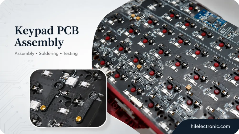
Keypad PCB Assembly Manufacturer | Custom Control Keypads
A keypad PCB assembly manufacturer may be building a...
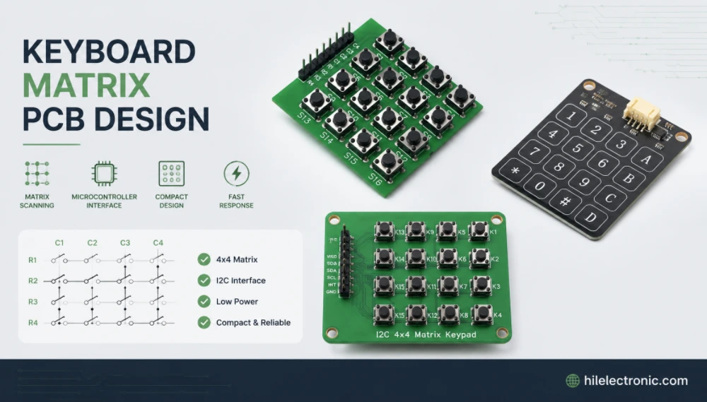
Keyboard Matrix PCB Design & Manufacturing | Anti-Ghosting
Keyboard matrix PCB design converts a large number of...
How to get a quote for PCBs
Let us run DFM/DFA analysis for you and get back to you with a report.
You can upload your files securely through our website.
We require the following information in order to give you a quote:
-
- Gerber, ODB++, or .pcb, spec.
- BOM list if you require assembly
- Quantity
- Turn time
In addition to PCB manufacturing, we offer a comprehensive range of electronic services, including PCB design, PCBA (Printed Circuit Board Assembly), and turnkey solutions. Whether you need help with prototyping, design verification, component sourcing, or mass production, we provide end-to-end support to ensure your project’s success. For PCBA services, please provide your BOM (Bill of Materials) and any specific assembly instructions. We also offer DFM/DFA analysis to optimize your designs for manufacturability and assembly, ensuring a smooth production process.