
Fiber Drum Electronics PCB Design | Control Systems for Fiber Drum Modules

In most real designs, the main control board is mounted on the stationary side of the drum assembly, where it can reliably control the motor, read sensors, monitor winding behavior, and support the interface between the drum mechanism and the rest of the system. In some specialized architectures, limited auxiliary sensing or interface elements may be placed on rotating structures, but that is a design choice rather than the default meaning of a fiber drum electronics PCB.
Get a Drum Electronics PCB Quote
Table of Contents
What Fiber Drum Electronics PCB Means in Practice
In practical engineering use, a fiber drum electronics PCB normally refers to the PCB assemblies associated with a fiber drum module rather than to a full control board fixed directly to the rotating drum. The drum is the mechanical storage and winding structure, while the electronics around it provide the control, sensing, interface, and monitoring functions needed for stable fiber handling.
Fiber Drum Subsystem Electronics Scope
- Drum motor-control electronics
- Winding and traverse-control circuitry
- Sensor-interface boards for position, tension, or thermal feedback
- Subsystem communications and status monitoring
- Support electronics near rotary or fiber handoff interfaces
Stationary PCB Architecture in Practical Designs
In most designs, keeping the main electronics on the stationary side improves serviceability, reduces rotational stress on components, and simplifies power and communication integration. Only specific sensing or auxiliary interface functions may be located on moving elements if the mechanism requires it.
This subsystem-level meaning is also why the topic overlaps naturally with tether spool PCB design, where the electronics support spool behavior, payout control, and fiber-management reliability as part of a larger deployment system.
Fiber Drum Electronics PCB Definition
The most accurate reading of the term is simple: a fiber drum electronics PCB is the PCB that controls and monitors the drum subsystem. It is a function-based term, not a requirement that the whole board spins with the drum.
Core Functions of a Fiber Drum Electronics PCB
The purpose of a fiber drum electronics PCB is to make the drum assembly controllable, measurable, and reliable during payout and retrieval. The exact implementation depends on the system, but most drum-side electronics combine several functional blocks.
Drum Motor Control Functions
- Drive drum rotation during payout or rewind
- Coordinate drum motion with a traverse or guide mechanism
- Regulate speed, torque, or winding-related behavior
- Report drum status to higher-level system electronics
Sensor Monitoring and Status Acquisition
- Measure drum position or rotation with encoders
- Read tension-related signals from load cells or guide structures
- Monitor local temperature near the motor or power stage
- Track end-of-travel, winding state, or subsystem fault conditions
Subsystem Communication and Interface Support
- Connect the drum subsystem to flight, payload, or ground-side control electronics
- Support wiring and monitoring near the fiber handoff region
- Provide fault signaling, health monitoring, and subsystem coordination
Where the drum belongs to a larger optical deployment architecture, these functions also connect to the broader fiber optic drone PCB system, especially where payout stability influences communication or guidance performance.
Winding Control and Length Estimation
One of the most valuable roles of a fiber drum electronics PCB is maintaining winding quality. A drum does not merely store fiber. It has to wind and unwind the fiber in a controlled way so the next deployment remains smooth and reliable. Poor winding behavior can create cross-overs, uneven layering, local compression, and tangling during later payout.
Winding Quality Control Objectives
- Prevent cross-over points that create snag or jam risk
- Reduce uneven layering that changes payout consistency
- Improve rewind quality for repeatable future deployment
- Maintain stable spool-state awareness during operation
Traverse and Drum Coordination Functions
- Coordinate drum rotation with traverse or guide position
- Control traverse reversal timing at layer transitions
- Monitor guide movement using encoder or actuator feedback
- Maintain consistent spacing across the drum width
Remaining Fiber Length Calculation Methods
Remaining-length estimation cannot always rely on raw drum revolutions alone, because the effective winding radius changes as layers build or unwind. More accurate electronics therefore use calibrated geometry models, layer-aware compensation, or other firmware correction methods to keep spool-state information meaningful.
This is one reason a fiber drum electronics PCB is more than a generic motor board. It has to support both motion and winding quality at the subsystem level.
Rotary Boundary and Interface Design
A fiber drum assembly almost always includes an important system boundary: the transition between rotating and stationary parts. Even when the main PCB remains on the stationary side, the system still has to cross that boundary through mechanical coupling, sensing, power transfer, or signal exchange.
Rotating-to-Stationary Interface Methods
| Method | Typical role | Main trade-off |
|---|---|---|
| Slip ring | Transfer power or electrical signals across rotation | Wear, contact noise, added size, filtering needs |
| Contactless transfer | Transfer selected power or data without sliding contact | Higher complexity, alignment sensitivity, efficiency trade-offs |
| Stationary electronics with indirect sensing | Keep most electronics fixed while only the drum rotates | Requires careful sensor placement and subsystem coordination |
PCB Requirements at the Rotary Boundary
If the architecture uses slip rings or other transfer interfaces, the PCB may require filtering, interface protection, and noise-tolerant communications. If the architecture keeps the electronics stationary, the board must infer drum behavior through external sensors, encoder coupling, or mechanism-level feedback.
On the ground or support side, the related management electronics may also connect to a canister PCB, depending on how the wider deployment system handles storage, payout, and optical continuity.
Mechanical and PCB Design Constraints
A fiber drum electronics PCB sits close to a mechanically active subsystem, so the board design has to account for more than electrical function alone. Even when stationary, the PCB may operate inside a confined drum housing with vibration, contamination risk, motor heat, and non-standard packaging constraints.
Mechanical Integration Constraints
- Limited space near the drum, motor, and guide structure
- Connector placement relative to rotating hardware
- Vibration from motor operation and airframe coupling
- Need for rigid mounting and low flex under load
PCB Layout and Partitioning Priorities
- Separate power, sensing, and digital-control areas clearly
- Keep high-current loops compact and thermally managed
- Protect analog sensor inputs from switching noise
- Preserve safe clearances near drum-side mechanics and routing paths
- Support custom outlines where the enclosure requires non-rectangular board shapes
Environmental Protection Requirements
- Dust or debris near the fiber path
- Temperature rise in enclosed housings
- Moisture or condensation risk in outdoor systems
- Contamination-sensitive areas near fiber handoff regions
Fiber Drum PCB Layout Strategy
The real PCB challenge is not how to mount a full board on a rotating drum, but how to design reliable drum-side electronics for a mechanically demanding subsystem. In most practical systems, that means stationary mixed-signal electronics designed around real drum constraints.
Fiber Drum Electronics PCB Manufacturing and Assembly
Because fiber drum electronics PCB refers to a subsystem board rather than to one fixed product shape, manufacturability depends on the actual functions included in the drum assembly. These boards often combine power electronics, sensor interfaces, digital control, connectors, and mechanical integration in one constrained design.
PCB Fabrication Requirements for Fiber Drum Electronics
- Custom outlines or special panelization where the enclosure demands it
- Stable copper distribution for power and sensing coexistence
- Mechanical reinforcement near encoders, connectors, and mounting points
- Process control that protects contamination-sensitive fiber-adjacent areas
PCB Assembly Requirements for Drum-Side Control Boards
- Mixed through-hole and surface-mount assembly
- Reliable soldering in current-carrying and feedback-critical regions
- Assembly consistency in mechanically stressed areas
- Clean handling around connector and fiber-adjacent regions
Functional Testing for Fiber Drum Electronics PCB
- Motor-drive and current-path verification
- Encoder and position-interface validation
- Sensor-chain calibration where required
- Boundary-crossing interface checks if transfer hardware is used
- Thermal and vibration-aware subsystem inspection
As a PCB fabrication and PCB assembly manufacturer, Highleap Electronics supports custom drum-side control boards for fiber-handling systems, including non-standard outlines, mixed-technology builds, mechanically constrained layouts, and subsystem-oriented assembly requirements. Highleap provides fabrication and assembly for specialized drone electronics. For related ground-side fiber management electronics, see the canister PCB page.

Recommended Posts

Per-Key RGB Keyboard PCB Manufacturer & LED Assembly
A per-key RGB keyboard PCB manufacturer must control far...

Ortholinear Keyboard PCB Manufacturer | Custom Grid Layout
An ortholinear keyboard PCB manufacturer must preserve a...
Keypad PCB Assembly Manufacturer | Custom Control Keypads
A keypad PCB assembly manufacturer may be building a...
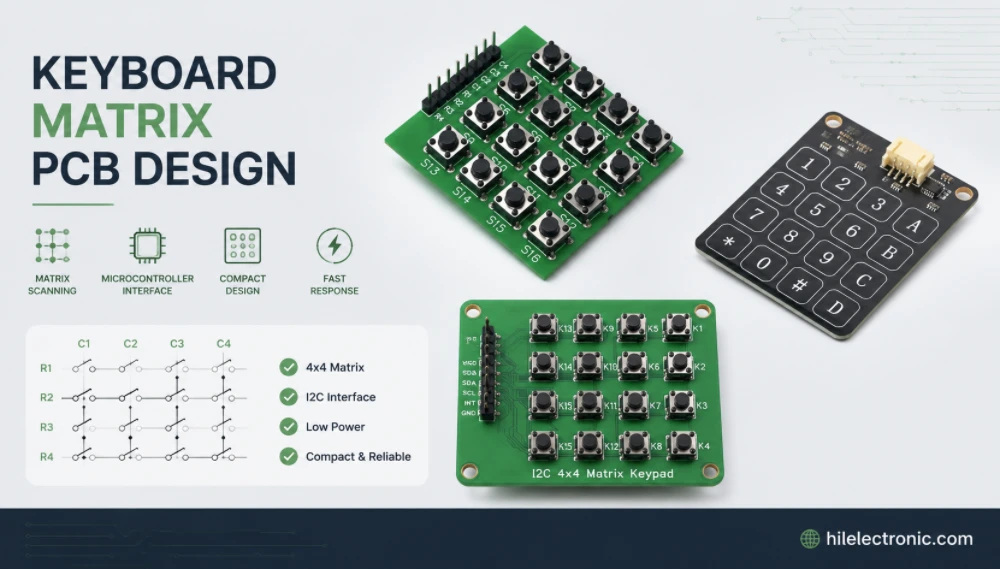
Keyboard Matrix PCB Design & Manufacturing | Anti-Ghosting
Keyboard matrix PCB design converts a large number of...
How to get a quote for PCBs
Let us run DFM/DFA analysis for you and get back to you with a report.
You can upload your files securely through our website.
We require the following information in order to give you a quote:
-
- Gerber, ODB++, or .pcb, spec.
- BOM list if you require assembly
- Quantity
- Turn time