
Ventec VT-481 PCB for Lead-Free Reliability
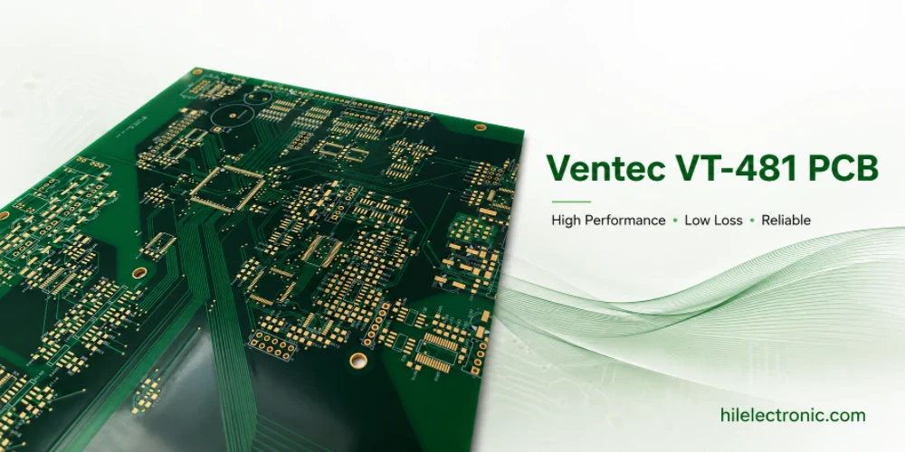
Ventec VT-481 is a mid-Tg, phenolic-cured FR-4.0 laminate and prepreg system intended for lead-free assembly, low z-axis thermal expansion, CAF resistance, and stable mainstream multilayer production. It should be selected when the dominant risk is interconnect and thermal reliability—not when the dominant problem is a long ultra-high-speed channel.
Ventec’s current public data identify VT-481 as a 155°C typical DSC Tg material with 345°C Td, T260 greater than 60 minutes, T288 about 25 minutes, 45 ppm/°C z-axis CTE below Tg, 220 ppm/°C above Tg, and 2.6% total z-axis expansion from 50–260°C. The construction tables show that Dk and Df vary with glass style and resin content; a representative 7628 construction is around Dk 4.30 at 1 GHz and Df 0.014 at 1 GHz. This is a reliability-focused material, not an ultra-low-loss laminate.
Start With the Failure Mechanisms, Not the Tg Number
A board can pass incoming inspection and fail only after assembly or field cycling. The failure may be a crack in a plated barrel, separation at an inner-layer junction, delamination near a copper plane, CAF leakage between biased vias, or warpage that disrupts BGA and connector assembly. These mechanisms are driven by the combination of material expansion, geometry, process, moisture, and thermal history.
| Failure mechanism | Primary drivers | Why VT-481 can help | What VT-481 cannot fix |
|---|---|---|---|
| PTH barrel fatigue | Z-axis expansion, board thickness, hole diameter, wall copper, reflow cycles, thermal cycling. | Low total z expansion reduces strain on the copper barrel. | Aggressive aspect ratio, poor plating, drill damage, or excessive rework. |
| Delamination | Moisture, incomplete cure, trapped volatiles, weak treatment, rapid heating. | Phenolic-cured high-reliability system and strong thermal-stress behavior support lead-free processing. | Wrong press cycle, contaminated surfaces, poor storage, or incompatible constructions. |
| CAF leakage | Humidity, bias, ionic contamination, glass/resin interfaces, drill damage. | Material is positioned for CAF resistance. | Insufficient conductor spacing, contamination, condensation, damaged hole walls. |
| Warpage | Asymmetric copper, unbalanced stack, pressure/temperature gradients, heavy components. | Stable FR-4 process base and controlled expansion support predictable builds. | Poor stack symmetry, copper imbalance, panel handling, or assembly fixture problems. |
| High-speed insertion loss | Dk/Df, copper roughness, trace geometry, length, vias/connectors. | Can support many moderate-speed routes with construction-specific modeling. | Long 56G/112G PAM4 channels requiring much lower distributed loss. |
This failure-map approach prevents the common mistake of selecting VT-481 only because “155°C Tg is high enough.” The reason to use the material should be linked to the actual risk: low z-axis expansion for holes, CAF resistance for humid biased structures, lead-free endurance for assembly, or a qualified broad construction range for production.
Why Z-Axis CTE Has More Board-Level Meaning Than Tg Alone
Tg indicates where the resin’s expansion and mechanical behavior change more rapidly, but it does not state how much the resin expands before or after that transition. For a plated hole, the strain imposed on the copper barrel depends strongly on the pre-Tg CTE, post-Tg CTE, total expansion over the actual temperature excursion, and the number of cycles.
| Property | What it tells the engineer | Limitation |
|---|---|---|
| Tg | Approximate transition in polymer behavior. | Does not directly quantify total barrel strain or fracture resistance. |
| Pre-Tg z-CTE | Expansion rate through the board before Tg. | Must be integrated over the actual temperature range and combined with geometry. |
| Post-Tg z-CTE | Expansion rate above Tg, often much higher. | Time above Tg and peak profile matter. |
| Total z expansion 50–260°C | Direct reference for cumulative thickness expansion over a lead-free excursion. | Still measured on a reference specimen, not the final thick board. |
| T260/T288 | Resistance to delamination at specified temperatures. | Does not replace PTH cycling or actual reflow/rework qualification. |
| Td | Thermal decomposition threshold under the stated test. | Normal assembly should remain far below decomposition; it is not the same as reflow endurance. |
VT-481’s low z-axis expansion is valuable because it reduces one source of barrel stress. The benefit is strongest when the design also uses reasonable finished holes, sufficient wall copper, stable drilling/desmear, and a controlled assembly profile. Material capability and board geometry multiply each other; one cannot be evaluated in isolation.
Model the Full Reflow, Wave, Selective-Solder, and Rework History
A supplier declaration of lead-free compatibility is only the starting point. The assembly process must be converted into an explicit thermal history. A board with two SMT reflows and no rework is different from a board that also sees wave solder, selective solder, connector touch-up, conformal-coating cure, and field repair.
| Process event | Thermal/mechanical concern | VT-481 planning action |
|---|---|---|
| First SMT reflow | Moisture expansion, initial resin/copper strain, BGA warpage. | Measure the board temperature, not only oven setpoints; define peak, ramp, and time above liquidus. |
| Second-side reflow | Cumulative strain and support of a partially assembled board. | Confirm bow/twist and interconnect margin after the first cycle. |
| Wave solder | Longer lower-side exposure, heavy through-hole and connector regions. | Thermocouple near high-mass copper and PTH fields; inspect representative holes. |
| Selective solder | Repeated local heating and steep gradients. | Define maximum local cycles and keep-out/fixture plan. |
| Press-fit insertion | Mechanical stress on plated holes after thermal exposure. | Coordinate hole/plating tolerances and connector insertion force. |
| Rework | High local temperature, long dwell, uncertain operator variation. | Set approved method, maximum cycles, temperature monitoring, and bake condition. |
| Field repair | Aged/moisture-exposed board receives another heat cycle. | Define moisture conditioning and repair acceptance. |
Use a representative preconditioning sequence
First-article and interconnect reliability coupons should experience the planned sequence before final inspection. If the board is expected to see two reflows, selective solder, and one authorized rework, the qualification should include that sequence or a justified conservative equivalent. Cross-sectioning a virgin coupon cannot prove post-assembly barrel integrity.
Design the Plated-Hole System Around the Thermal Load
The plated-hole system includes the laminate, drill, hole wall, desmear, electroless copper, electrolytic plating, annular ring, inner-layer junction, finished hole, and any press-fit or solder load. VT-481 reduces resin expansion, but the copper still must be designed and deposited to survive the imposed strain.
| Hole variable | Reliability effect | Release control |
|---|---|---|
| Finished board thickness | Longer barrel sees more total differential expansion. | Use actual finished thickness and local copper build in the aspect-ratio review. |
| Finished hole diameter | Smaller diameter generally increases aspect ratio and process difficulty. | Avoid unnecessarily small holes; define drill and finished tolerances. |
| Wall copper | Thin or uneven plating has lower fatigue margin. | Specify minimum finished wall copper by product class and verify distribution. |
| Drill quality | Smear, glass damage, roughness, and nail-heading weaken the interface. | Control tool life, hit count, chip load, stack height, entry/backup and microsections. |
| Desmear | Under-desmear leaves resin; over-desmear attacks glass/resin interfaces. | Qualify chemistry/plasma for VT-481 construction and inspect hole walls. |
| Annular ring and registration | Offset can reduce pad capture and concentrate stress. | Set registration capability, pad size, and cross-section locations. |
| Press-fit geometry | Insertion force adds mechanical strain after fabrication. | Coordinate finished-hole tolerance, plating thickness, connector pin, and mechanical test. |
Aspect ratio is not a single universal limit
A fabricator’s advertised maximum aspect ratio may describe a capability under selected conditions, not a robust production rule for every hole size, layer count, copper weight, and reliability class. The approved ratio should be based on plating distribution, drill quality, thermal history, and customer qualification. For high-reliability boards, using less than the theoretical maximum often provides more value than choosing a higher-Tg material.
CAF, Moisture, and Cleanliness Controls
VT-481 is positioned for CAF resistance, but CAF remains a system failure. A conductive path can develop along glass/resin interfaces when moisture, ionic species, electric bias, and a susceptible path coexist. Dense via fields and small plane clearances can create high local electric fields.
| CAF/moisture factor | Design or process control |
|---|---|
| Conductor voltage and spacing | Create spacing rules by voltage, environment, coating, and product life; include vias, planes, pads, and board edges. |
| Humidity and condensation | Define enclosure, sealing, drainage, coating, venting, and humidity-bias qualification. |
| Material storage and bake | Follow laminate/prepreg storage, shelf-life, package reseal, and assembly moisture controls. |
| Drilling and desmear | Prevent glass/resin separation and damaged migration paths; use representative microsections. |
| Ionic cleanliness | Control fabrication and assembly rinsing, residues, handling, and customer-required cleanliness tests. |
| Solder mask/coating | Verify coverage, cure, adhesion, edge protection, and compatibility with high-voltage spacing. |
| Glass style substitution | Do not change construction casually; glass/resin architecture affects CAF and dielectric behavior. |
Fabrication Controls From Lamination Through Plating
Ventec publishes detailed storage, press, construction, and drilling guidance for VT-481. Production should use the current processing guideline and the fabricator’s qualified equipment window. The most important control is consistency between the approved construction and the actual material, press, drill, desmear, and plating process.
- Verify incoming material. Confirm exact laminate/prepreg, glass style, resin content, copper foil, lot, shelf life, storage and package condition.
- Review resin demand. Use actual copper distribution and selected prepreg plies to avoid voids, starvation, and thickness drift.
- Control material temperature during lamination. Record heating rate, cure temperature/time, pressure, and vacuum on the qualified stack.
- Measure finished thickness and registration. Include panel edge/center and dense/sparse copper regions on the first article.
- Use hole-size-specific drilling. Control hit count and tool life; do not apply one parameter set to all diameters.
- Qualify desmear and plating. Verify resin removal, glass condition, copper adhesion, wall thickness and distribution.
- Protect moisture condition. Seal, store, stage, bake when justified, and minimize uncontrolled floor life.
Thin cores and copper profile
Ventec notes handling and copper considerations for thin cores. Thin cores can be damaged or distorted, and copper-profile changes affect peel strength, impedance, and loss. The stackup should specify the approved foil and the fabricator should control any change as an engineering revision rather than a purchasing convenience.
Where VT-481 Fits—and Where It Does Not
| Application/board | VT-481 fit | Boundary |
|---|---|---|
| Industrial control and instrumentation multilayers | Strong candidate for robust lead-free and PTH reliability. | Verify service temperature, voltage spacing, holes, and moisture environment. |
| Automotive control electronics | Candidate subject to customer/automotive qualification. | Not a substitute for AEC/automotive process and mission-profile validation. |
| Communication control boards | Good where route loss is moderate and reliability dominates. | Long high-speed channels may need a lower-loss material. |
| Connector-rich backplanes at moderate speed | Potential fit because PTH and press-fit reliability matter. | Quantify route length and loss; do not use on high-speed reach by category alone. |
| High-voltage humid equipment | Potential fit with CAF controls. | Spacing, coating, cleanliness, condensation, and bias test remain mandatory. |
| Long 112G PAM4 backplane | Usually not the first choice. | VT-481 Df is in a standard/mid-loss range; evaluate a dedicated low-loss system. |
| 77 GHz antenna or precision RF layer | Not appropriate as the default. | Use a frequency-specific RF laminate and module-level validation. |
The application name is not the selection criterion. An automotive board with only short control signals may fit VT-481 well; a communication board with a long PAM4 backplane may not. Use the board’s actual thermal, electrical, voltage, moisture, and interconnect stresses.
Qualification and Production Monitoring
Qualification should connect each risk to evidence. A low-z-CTE claim is verified through as-built holes and thermal exposure; CAF is verified through process controls and environmental test; dimensional stability is verified by stackup and warpage measurements.
- Material and stackup: CoC, exact construction, pressed thickness, glass, resin content, copper and lot traceability.
- Hole microsections: smallest, highest-aspect-ratio, press-fit, heavy-copper and thermally stressed locations.
- Thermal preconditioning: representative reflow/wave/selective/rework sequence before final inspection.
- PTH reliability: customer/IPC thermal cycling, solder-float, IST or other approved method for the actual geometry.
- CAF/insulation: humidity-bias and cleanliness evidence where the mission profile requires it.
- Warpage: bow/twist before and after assembly exposure, using defined support and temperature conditions.
- Electrical: impedance and construction-specific Dk/Df control for moderate-speed routes.
- Production monitoring: trend wall copper, thickness, registration, thermal profile, material lot and selected coupon results.
The release baseline should include approved microsection images and raw measurements. Future changes to prepreg construction, copper foil, press cycle, drill supplier, desmear, plating chemistry, panel size, or assembly profile can then be assessed against a traceable reference.
RFQ for a Low-Z-CTE Reliability Board
| RFQ field | What to state |
|---|---|
| Exact material | Ventec VT-481 laminate and matching prepreg, construction, glass style, resin content, copper, controlled datasheet/processing revision. |
| Reliability purpose | Low z-axis expansion/PTH, CAF, lead-free endurance, dimensional stability, or specified customer requirement. |
| Geometry | Layer count, thickness, copper, smallest holes, drill/finished sizes, aspect ratios, via density, press-fit and heavy-copper areas. |
| Thermal history | SMT sides/cycles, peak and time above liquidus, wave/selective solder, rework limit, bake and storage. |
| Environment | Operating/storage temperature, humidity, condensation, voltage/spacing, coating, cleanliness, expected field cycles. |
| Process controls | Lamination, resin fill, registration, drilling, tool life, desmear, plating, wall copper, bow/twist. |
| Evidence | CoC, stackup, press record, microsections, plating data, preconditioning, PTH/CAF tests, warpage and electrical coupons. |
| Substitution | No replacement based on Tg alone; require CTE/expansion, thermal, CAF, construction, process and board-level comparison. |
The RFQ should also define which construction changes the fabricator may propose. A different glass-style combination may improve resin fill or thickness availability, but it changes Dk, pressed thickness, drilling, and potentially CAF behavior. Approval should occur before artwork compensation and qualification.
Reliability Questions That Need Specific Answers
Does 155°C Tg make VT-481 a high-reliability material by itself?
No. Its value comes from the complete thermal and reliability package, especially low z-axis expansion and lead-free process performance. Board geometry, plating, moisture, and assembly history remain decisive.
Is baking always required before assembly?
Not automatically. Bake decisions should follow material/board moisture condition, storage and floor life, assembly profile, component limits, and the fabricator/assembler’s qualified procedure. Unnecessary or excessive baking can also age finishes and materials.
Can VT-481 be used with heavy copper?
Ventec lists a broad copper availability, but heavy copper increases resin demand, etch difficulty, thermal mass, and warpage risk. The exact construction and process require review and qualification.
What matters most for hole reliability?
The combination of total z expansion, finished thickness, hole diameter, wall copper, drill/desmear quality, reflow/rework history, and field cycling. No single datasheet property replaces that combination.
When should a lower-loss material be selected?
When the complete channel—not the product label—shows that distributed dielectric/conductor loss consumes the margin after vias, connectors, topology, and copper have been optimized.
VT-481 is therefore a practical PCB reliability material when used with a board-specific stress model. The engineering content should center on failure prevention and evidence, not a generic list of properties.
Manufacturer references and release notes
The Ventec page below provides the construction tables and typical thermal, expansion, and dielectric references used in this guide. Production documentation should freeze the current controlled VT-481 datasheet revision, actual glass/resin construction, copper option, and agreed qualification evidence.

Recommended Posts

Taconic RF 35 vs RO4350B PCB
Table of contentsRF-35 vs RO4350B Procurement and...

TMM4 Filter PCB Manufacturing
TMM4 filter PCB manufacturing is controlled by the...

TMM3 PCB Manufacturing for RF Modules
TMM3 PCB manufacturing is most useful where the RF module...

TMM6 PCB Fabrication
TMM6 fabrication is the process-control page for a mid-Dk...
How to get a quote for PCBs
Let’s run DFM/DFA analysis for you and get back to you with a report. You can upload your files securely through our website. We require the following information in order to give you a quote:
-
- Gerber, ODB++, or .pcb, spec.
- BOM list if you require assembly
- Quantity
- Turn time
For PCBA services, please provide your BOM (Bill of Materials) and any specific assembly instructions. We also offer DFM/DFA analysis to optimize your designs for manufacturability and assembly, ensuring a smooth production process.