
ZMK Keyboard PCB Manufacturing & Assembly
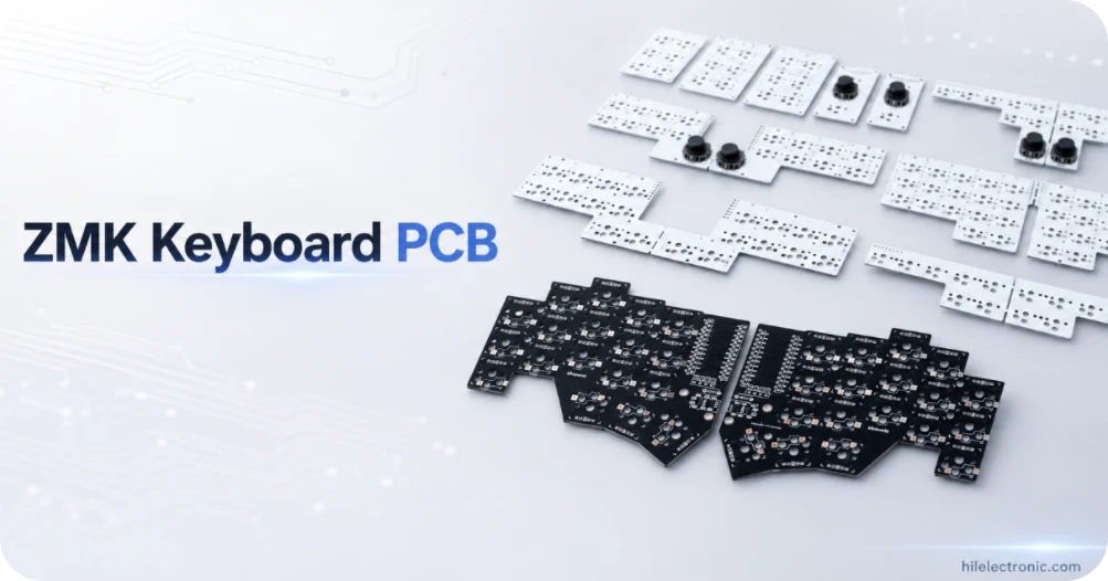
ZMK is commonly selected for low-power Bluetooth keyboards, split keyboards and battery-operated input devices, especially when compact controller modules or Nordic-based wireless hardware are used. Highleap Electronics manufactures PCBs and assembled PCBAs for a wide range of electronic products, not only keyboard applications. For ZMK projects, services can cover rigid PCB fabrication, controller-module or chip-down BLE assembly, USB-C and charging circuits, displays, encoders, RGB, batteries, left/right programming, wireless pairing, current testing and final product integration.
A repository or keymap alone is not a complete manufacturing package. The released PCB revision, controller pins, bootloader, devicetree configuration, generated binaries, left/right roles, battery behavior, bond-clear process and test procedure must all agree. Highleap converts the approved development data into controlled production instructions so every ZMK PCBA is programmed, identified and tested against the correct product variant.
ZMK Wireless Keyboard PCBA Procurement Guide
Highleap can manufacture a ZMK split keyboard PCB, nRF52-family keyboard PCB, module-based wireless keyboard or chip-down ZMK BLE keyboard. ZMK firmware flashing, bond clearing, left/right identification and host pairing can be included in the production route. Custom keyboard hardware remains build-to-print: Highleap does not alter the customer keymap or wireless architecture without approval.
| Procurement item | Highleap supply and quotation basis |
|---|---|
| Hardware formats | Controller-module carrier PCB, chip-down BLE PCB, wired/wireless hybrid, split pair or receiver/dongle architecture. |
| Firmware inputs | Released left/right binaries, bootloader, ZMK configuration archive, keymap, recovery instructions and version identifier. |
| Wireless functions | BLE advertising, profiles, pairing, reconnect, split central/peripheral roles and battery reporting as defined. |
| Assembly | BLE controller/module, crystals, USB-C, charger, battery connector, keys/sockets, displays, encoders and RGB. |
| Test | Programming, role identification, bond clear, half pairing, host pairing, matrix, USB, current and optional display/RGB checks. |
| Prototype MOQ | Initial ZMK PCB assembly can use Highleap’s 5-piece low-MOQ entry point. For split products the quotation states whether quantity is counted by individual half or complete pair, and controller modules, batteries and pairing time may change the minimum. |
| Lead-time commitment | ZMK delivery is confirmed after controller/module stock, batteries, bootloader, released binaries, role definitions and pairing test are available. The assembly lead-time reference covers fabrication and sourcing; firmware-build or wireless-debug time is excluded unless separately scoped. |
| Cost drivers | Controller availability, module vs chip-down design, split pair handling, battery, programming time, pairing/serialization and test fixture complexity. |
| Preferred quotation files | Provide Gerber/ODB++, drills, BOM, centroid and drawings plus controller data, bootloader, released left/right binaries, configuration archive, keymap, battery/enclosure information and pairing/test steps. Highleap’s file checklist supplies the base manufacturing formats. |
| Software boundary | Highleap can build and flash the approved release. New ZMK feature development, application debugging and certification are separate scopes unless contracted. |
Highleap’s rigid-board capability supports both module carriers and chip-down BLE designs. The actual ZMK build is constrained by antenna clearance, controller escape, battery circuit, split-half geometry and programming access, so a DFM-approved subset is documented for each revision.
ZMK Wireless Keyboard Hardware and Production Files
ZMK is an open-source keyboard firmware built on Zephyr and designed for wired and wireless input devices. Its official documentation lists wireless split keyboards, low active power and sleep states among supported capabilities: ZMK introduction and feature status. For manufacturing, Highleap needs the exact hardware and configuration rather than a general request for “ZMK support.”
For ZMK keyboard PCB production, control extends beyond soldering. Highleap identifies each hardware variant, flashes the correct firmware, verifies the shipping bond state and records the released ZMK PCBA revision. Wireless split products receive pair-level testing rather than two unrelated board tests.
The broader RF, battery and antenna production controls are covered on the wireless mechanical keyboard PCB service page.
| Required file or decision | Why it matters | Release condition |
|---|---|---|
| Controller board or SoC | Defines pins, radio, bootloader and supply requirements | Exact part and approved source. |
| ZMK board/shield configuration | Maps hardware nodes, matrix, sensors and split roles | Repository commit or controlled archive. |
| Left/right or central/peripheral builds | Prevents firmware being loaded to the wrong half | Named binaries and programming instruction. |
| Keymap and feature configuration | Defines inputs, lighting, encoders and profiles | Approved version for production test. |
| Battery and charger specification | Defines power and safety behavior | Approved schematic, pack and limits. |
| Test commands and reset/bond procedure | Enables repeatable pairing and functional test | Operator instruction and pass/fail criteria. |
Highleap can build engineering prototypes while configuration is evolving, but repeat production requires a frozen PCB, BOM, firmware repository state and test revision.
Controller, Pin Assignment and Bootloader Control
ZMK designs commonly use nRF52-based modules or controller boards, but the manufacturing review follows the exact customer selection. Highleap checks matrix pins, I²C/SPI devices, encoders, displays, battery measurement, external-power control, USB and programming access against the devicetree files.
- confirm every schematic net matches the ZMK pin assignment and board definition;
- reserve programming and recovery access for the selected controller;
- verify oscillator, antenna, regulator and decoupling requirements for custom SoC layouts;
- define the bootloader image, application image and flash sequence;
- protect USB-C, battery and exposed connector interfaces;
- document optional hardware variants so the correct binary is loaded.
Programming can be integrated with microcontroller board soldering and programming. Highleap records the approved image name or checksum with the production lot.
ZMK Split Keyboard Roles, BLE and Power Domains
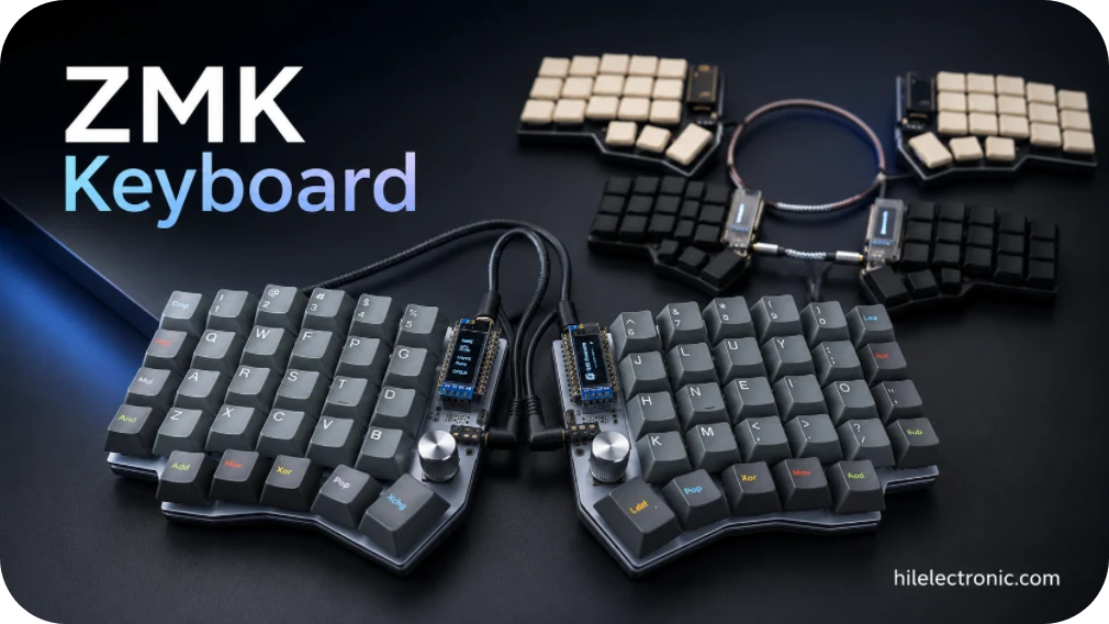
ZMK split keyboards use a central device that processes keymap state and communicates with the host, while peripheral parts send key or sensor events. The central normally consumes more power because its radio activity is greater. These roles and the pairing procedure are documented in the ZMK split keyboard guide.
Matched left/right production, spare-half policy and packing are detailed in split keyboard PCB manufacturing.
| Design area | ZMK production concern | Highleap test |
|---|---|---|
| Central/peripheral identity | Wrong firmware prevents correct role operation | Flash labelled binaries and verify role behavior. |
| BLE pairing between halves | Stored bonds can prevent a new matched set from connecting | Use controlled clear/reset/pair sequence. |
| Host profiles | Old bonds can cause failed reconnects | Clear profiles and test approved host switching. |
| Battery difference between halves | Central and peripheral current can differ | Measure each side in defined states. |
| External-power rail | Displays or lighting can drain batteries while nominally off | Verify firmware-controlled rail shutdown. |
| USB access | Only intended side may expose host or charging functions | Test both halves against product instruction. |
For wireless split products, Highleap can serialise and pack halves as matched pairs. Spare-half policy and replacement pairing should be defined before production because after-sales units may need a dedicated reset and bonding procedure.
ZMK Keyboard PCB Manufacturing Specifications
The following values are taken from the published Highleap rigid PCB capability table. They are factory-level limits, not a promise that every extreme can be combined in one build. ZMK products can range from small controller boards to long keyboard halves. The practical manufacturing route depends on the selected module/SoC, antenna, matrix density, battery connector and mechanical outline.
| Manufacturing item | Published Highleap capability | Project condition |
|---|---|---|
| Maximum layer count | Up to 60 layers | Actual stackup is released after DFM review. |
| Minimum inner/outer trace and space | 2/2 mil | Copper weight, board size and process combination can change the practical limit. |
| Finished board thickness | 0.2–8.0 mm | Keyboard mechanical stack and connector height usually control the selected thickness. |
| Finished board size | 10 × 10 mm minimum; 22.5 × 47.5 in maximum | Panel utilisation, outline shape and assembly support must be reviewed. |
| Outline tolerance | ±0.1 mm | Critical switch, plate and enclosure interfaces should be dimensioned on the drawing. |
| Minimum laser drill / annular ring | 0.075 / 0.075 mm | Microvias are used only when routing density justifies HDI processing. |
| Published impedance tolerance | ±5 Ω at ≤50 Ω; ±7% above 50 Ω | Relevant to USB, RF and other controlled-interconnect designs. |
| Minimum SMT pad capability | 7 × 10 mil | Component package and paste aperture remain subject to assembly review. |
| Minimum BGA pitch | 7 mil | Final package assembly depends on pad design, stencil, via strategy and inspection plan. |
| Published surface finishes | ENIG, ENEPIG, OSP, HASL, immersion silver/tin, hard gold and others | Finish is selected for solderability, contacts, cost and storage requirements. |
Highleap can fabricate two distinct split halves, mirrored variants or a shared reversible PCB when the design supports it. Each variant receives a controlled fabrication and assembly identifier to prevent mixing during programming and packing.
ZMK Firmware Flashing, Pairing and Functional Test
The production station should be able to recover a blank or incorrectly flashed controller, not only test a unit that was programmed manually by the developer. Highleap requests the bootloader, application files, programmer, cables, scripts and failure-recovery instruction before NPI.
Highleap can implement these steps within a documented keyboard PCBA testing station.
- Program: load bootloader and ZMK application using the approved interface.
- Identify: record left/right, central/peripheral and hardware variant.
- Clear bonds: place the device in a known pairing state.
- Pair halves: verify split communication and key events from both sides.
- Pair host: test BLE advertising, connection and profile switching.
- Exercise hardware: matrix, encoder, display, lighting, battery reporting and USB.
- Measure current: active, idle and sleep states under the defined firmware.
- Store result: associate firmware/test revision with the unit or lot.
ZMK supports multiple Bluetooth profiles by default and stores bond information, so the shipping state and profile-clear procedure must be defined: ZMK Bluetooth profiles and pairing.
Representative ZMK Hardware Production Routes
These representative routes show how the manufacturing package changes between common ZMK architectures.
| Representative configuration | Typical hardware scope | Production and acceptance focus |
|---|---|---|
| Controller-module wireless board | Socketed or soldered BLE controller module, battery and USB-C | Module orientation, programming, current, pairing and mechanical height verification. |
| Chip-down ZMK product | BLE SoC, RF network, crystal, antenna, charger and keyboard matrix | RF geometry, X-ray where required, programming, current and wireless functional test. |
| ZMK wireless split pair | Separate left/right PCBAs with central/peripheral roles | Correct binaries, pair identification, inter-half communication, host pairing and spare-half policy. |
MOQ, Prototype-to-Production Revisions and Delivery
ZMK projects often change quickly during development. Highleap separates experimental builds from released production by controlling the repository state, generated binaries, PCB revision, BOM and test script together. A firmware change can alter HID behavior, sleep current or required hardware testing even when the PCB is unchanged.
Pilot demand can use high-mix low-volume PCB assembly, while controlled parts are managed through component sourcing.
| Controlled item | Example change | Required action |
|---|---|---|
| PCB revision | Pin, connector, antenna or battery change | New DFM and first-article review. |
| BOM/AVL | Controller, regulator or display alternate | Compatibility and sourcing approval. |
| ZMK configuration | Matrix, split, HID or power option | Rebuild, flash and regression test. |
| Bootloader | Recovery or flash-interface change | Update production programmer and instruction. |
| Test script | New feature or acceptance limit | Fixture validation and operator release. |
| Packaging/labels | Left/right, battery or country marking | Update traceability and packing control. |
Highleap supports prototypes, high-mix low-volume orders and scheduled production. The lead time is committed after controller supply, firmware readiness, fixture scope and battery handling are confirmed.
Highleap Production Controls for ZMK Projects
- PCB, BOM, bootloader, binaries and test scripts are linked by revision.
- Left/right and central/peripheral identities are controlled during programming and packing.
- Current consumption can be measured under the customer-approved firmware state.
- Module-based prototypes can transition to a controlled chip-down or volume design.
- Replacement halves and after-sales pairing procedures can be defined before launch.
ZMK Keyboard PCB Manufacturing FAQ
These questions address the most common production searches for ZMK wireless, split and nRF52-based keyboard PCB assemblies.
What is a ZMK keyboard PCB and how is it different from a QMK keyboard PCB?
ZMK is built for Zephyr RTOS and is widely used for Bluetooth and low-power keyboards. QMK is more established for wired and feature-rich keyboard firmware, although wireless implementations also exist. The PCB choice depends on the MCU, radio architecture, power target, required features and the firmware ecosystem selected by the product owner.
Should a ZMK keyboard use a controller module or a chip-down nRF52 design?
A module can reduce RF design risk and simplify low-volume sourcing, but it may cost more and limit mechanical placement. A chip-down design can reduce unit cost and size at higher volumes, while requiring controlled RF layout, antenna design, crystals, programming access and certification planning.
What ZMK files are required for PCB assembly and firmware programming?
Provide Gerber or ODB++, drill, schematic, BOM, centroid and assembly drawings together with the controller definition, bootloader, released left and right binaries, ZMK configuration archive, keymap, version identifier, programming method, bond-clear instructions and functional test procedure.
Why do ZMK split keyboards need different firmware for the left and right halves?
The two halves may use different matrix pins and central or peripheral roles. Production must load the correct image into each side, label the assemblies and verify that they connect to each other and to the host. Reversible hardware still needs a defined method for assigning its final role.
How are Bluetooth pairing and bond clearing tested on a ZMK keyboard?
A production procedure can erase old bonds, program the released image, pair the split halves, connect to a controlled host and verify reconnect behavior. The shipping state should be defined so the end user receives a clean device or a pre-paired set according to the product plan.
How can ZMK keyboard battery life be improved?
Low-power performance depends on controller selection, regulator efficiency, matrix scanning, display and RGB behavior, advertising intervals, sleep states and leakage from external circuits. Firmware optimization and hardware measurement are separate tasks; production can verify current limits after the approved design is released.
Can a ZMK keyboard use a USB dongle instead of connecting directly by Bluetooth?
Yes, a customer-defined dongle architecture can be manufactured when both keyboard and receiver hardware, firmware, pairing method and test criteria are provided. The dongle is an additional product variant and should have its own BOM, firmware, identifiers and traceability.
What affects the MOQ and lead time for ZMK keyboard PCB assembly?
Controller-module availability, nRF52 components, batteries, displays, left/right quantities, firmware readiness, programming fixtures and pair-level testing influence the practical minimum and schedule. For split products, the quotation should clearly state whether quantity is counted by half or complete pair.
Can paired ZMK split keyboard PCBAs be supplied as a complete assembly?
Yes. Highleap can manufacture, program, pair, test, label and package matched left/right PCBAs, and can add batteries, enclosures or final box build when the mechanical package and product acceptance criteria are complete.

Recommended Posts

TMM4 Filter PCB Manufacturing
TMM4 filter PCB manufacturing is controlled by the...

TMM3 PCB Manufacturing for RF Modules
TMM3 PCB manufacturing is most useful where the RF module...

TMM6 PCB Fabrication
TMM6 fabrication is the process-control page for a mid-Dk...

TMM10 PCB Manufacturing for Compact RF Designs
Table of contentsHow TMM10 Shrinks RF StructuresTMM10 vs...
How to get a quote for PCBs
Let’s run DFM/DFA analysis for you and get back to you with a report. You can upload your files securely through our website. We require the following information in order to give you a quote:
-
- Gerber, ODB++, or .pcb, spec.
- BOM list if you require assembly
- Quantity
- Turn time
For PCBA services, please provide your BOM (Bill of Materials) and any specific assembly instructions. We also offer DFM/DFA analysis to optimize your designs for manufacturability and assembly, ensuring a smooth production process.