NAS PCB Manufacturing for Backplanes and Control Boards
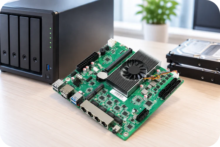
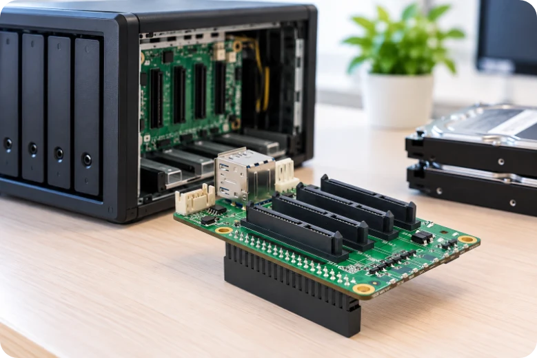
Highleap Electronics manufactures customer-released NAS PCBs and PCBAs including drive backplanes, controller/main boards, power-distribution boards and auxiliary I/O assemblies. We quote multilayer fabrication, component sourcing, SMT/THT assembly, inspection, programming and customer-defined test according to the released SATA, SAS or PCIe/NVMe architecture. Production review links board revisions, drive connectors, power distribution, chassis datums, firmware and bay-level test into one controlled build package.
Map NAS Enclosure Types and the PCB Set Used in Each Product Class
The first sourcing mistake to avoid is treating “NAS enclosure PCB” as a single product category. A two-bay consumer NAS and a multi-bay storage server can use very different board sets. Before quoting, the OEM should identify which PCBs Highleap is expected to fabricate/assemble and which functions remain part of purchased modules or the final system.
NAS hardware is a system family, not a single “NAS enclosure PCB.” Different products combine controller/main boards, SATA/SAS/NVMe backplanes, power-distribution boards, front-panel I/O, fan boards and other assemblies in different ways. Product classification is therefore useful both for search coverage and for defining which PCB/PCBA Highleap is actually being asked to manufacture.
NAS Product Families Extend From 2-Bay Desktop Units to All-Flash and Rack Systems
- 2-bay desktop NAS: A compact entry-level system that may place drive connectors directly on a main board or use a small backplane. Mechanical alignment, fan/airflow constraints and shared startup power dominate a relatively small enclosure.
- 4-bay desktop NAS: Adds more drive connectors and power branches and is a common point where a dedicated backplane becomes more attractive. Bay-to-bay connector position and sequential functional test need tighter fixture control.
- 6-bay / 8-bay NAS: Increases backplane length, power distribution, fan integration and cable/board interconnect complexity. More bays also make SKU/revision control important because one chassis family may support several CPU/network variants.
- Rackmount NAS / storage server: Uses a chassis and backplane architecture closer to server/storage equipment, often with more serviceable drive bays, redundant or higher-capacity power systems, fan modules and management interfaces according to the OEM design.
- SATA NAS: Uses SATA drive interfaces where specified. PCB manufacturing priorities include drive-connector datum, backplane channel integrity, power branches and hot-swap/support circuitry as defined by the design.
- SAS/SATA storage backplane: Some NAS or storage-server platforms use SAS/SATA-compatible backplanes. This is a different high-speed/backplane class and should not be assumed on a consumer NAS unless the product release explicitly specifies it.
- NVMe / all-flash NAS: Uses PCIe/NVMe storage rather than a conventional SATA-only architecture. Higher-speed channel routing, connector selection, retimers/switches where present, thermal density and power distribution become much more demanding.
- Hybrid NAS with SATA plus NVMe: Combines disk bays with NVMe devices for cache, tiering or all-flash functions according to system architecture. The main board and backplane may therefore contain both SATA and PCIe/NVMe routing domains.
- High-speed network NAS: Adds 2.5GbE, 5GbE, 10GbE or another network interface only when the OEM platform specifies it. Network PHY/controller, magnetics, thermal load and connector configuration can materially change the main-board PCBA.
- Hot-swap NAS backplane: Focuses on repeatable drive mating, power-control/support circuitry and bay identification. It should be discussed as a backplane manufacturing program rather than as a complete NAS motherboard.
- JBOD / DAS storage chassis: Adjacent multi-bay storage products may share backplane, power and mechanical technologies with NAS but omit the networked compute platform. They are useful related product categories without being mislabeled as NAS.
| Product class | Typical architecture emphasis | Manufacturing / test priority |
|---|---|---|
| 2–4 bay desktop NAS | Compact controller + small backplane or direct connectors | Connector datum, startup power, airflow |
| 6–8 bay NAS | Larger backplane and shared power | Backplane flatness/alignment, bay FCT, fan/power integration |
| Rackmount storage server | Serviceable bays + management/power modules | Backplane reliability, replaceable modules, system fixture strategy |
| All-flash / NVMe NAS | PCIe/NVMe storage fabric | High-speed stack-up, connector/switch/retimer assembly, thermal density |
This family structure broadens exposure to NAS backplane PCB, 4-bay NAS PCB, rackmount NAS PCBA, NVMe NAS PCB and storage server backplane searches, while keeping the page accurate about what is actually being built: one or more defined PCB assemblies inside a larger storage system.
Map the NAS Board Set Before Manufacturing
| Board type | Typical role in the system | Primary manufacturing risks |
|---|---|---|
| Drive backplane | Connects multiple drives to the controller and distributes power/status signals | Repeated connectors, high-speed routes, hot-plug mechanics, power distribution |
| Controller / main board | Runs processor/SoC, memory, network and storage-control logic | BGA/DDR/high-speed routing, dense power, programming and system test |
| Power-distribution board | Routes adapter/PSU power to drives and other boards | High-current copper, connectors, protection and thermal rise |
| Front I/O / LED board | Buttons, indicators, USB, display or service controls | Cable/connector orientation, panel alignment and variant labeling |
| Drive-tray / interconnect board | Local connector/LED/management interface in some systems | Mechanical mating, repeated insertion and cable/board-to-board fit |
A NAS server PCB fabrication program can include several of these assemblies. The manufacturing release should therefore use board-level part numbers and revisions, not only the enclosure model name. This prevents a change to one small front-panel PCB from being confused with a mainboard or backplane revision.
Define System Interfaces Without Assuming the Storage Protocol
- SATA backplane: Uses Serial ATA links and SATA drive connectors as released. The backplane should not be called NVMe simply because the NAS uses SSDs.
- SAS backplane: Used in some server/storage products and has a different controller/cabling ecosystem. SAS applies only when it is part of the released controller, drive and backplane architecture.
- PCIe/NVMe backplane: Routes PCIe to NVMe drives or modules and can require different connectors, lane mapping, retimers/switches and high-speed fabrication controls.
- Network interface: Ethernet speed and PHY architecture belong to the controller/main board and are independent of whether the internal drives use SATA or NVMe.
- Management signals: LEDs, presence detect, fan control, temperature sensing or management buses should be documented as part of the exact product—not inferred from the word NAS.
This board-set definition also clarifies which adjacent manufacturing capability is relevant. A storage server PCB may share backplane and controller-board technology with a NAS, but server-class features, redundancy and interface choices are product-specific.
Manufacture Multi-Drive Backplanes to the Chassis Datum
The drive backplane is usually the most mechanically repetitive PCB in a multi-bay NAS. It carries multiple drive connectors at fixed spacing, often near board edges or tray guides, and may carry high-speed links plus power. Connector position and board flatness can therefore be as important as electrical continuity.
Backplane Manufacturing Controls
- Release connector pitch from the chassis datum: The backplane PCB drawing should identify the mechanical reference that aligns every drive bay. Small cumulative spacing error across several connectors can make outer bays difficult to insert even when each footprint is nominally correct.
- Control repeated high-speed routes by channel: SATA/SAS or PCIe routes should follow the released stack-up, impedance, reference planes and connector breakout. Repeated lanes should not be “cleaned up” independently by CAM in ways that make one bay different from another.
- Protect connector coplanarity: Large repeated connectors can warp or shift during soldering. First article should verify height and angular alignment with a gauge or representative drive-tray fixture.
- Plan insertion-force support: Board mounting and chassis features should carry repeated drive insertion loads. Solder joints should not be the only mechanical retention where the enclosure design provides supports.
- Keep hot-plug implementation design-specific: A backplane may be used in a hot-plug product, but the exact power sequencing, connector design and controller support must come from the OEM architecture. Manufacturing should not claim hot-plug capability from the connector alone.
For an NVMe NAS backplane PCB, the PCIe lane map, connector definition, retimers/switches if present and reference-clock/reset topology are critical release data. The fabricator can reproduce those high-speed structures; it should not infer lane width or PCIe generation from the drive form factor or from “NVMe” in the product name.
Backplane Yield Should Be Measured by Bay
When a multi-bay backplane is tested, results should identify the physical bay. Repeated failures at the same position can point to connector fixture alignment, one routed channel, local power distribution or a panel/mechanical issue. A single pass/fail result for the entire backplane throws away this diagnostic advantage.
Control Drive Power Distribution and Startup Loads
Multi-drive systems can create large startup and steady-state load on the backplane or power board. The exact current depends on drive type, staggered startup policy, PSU design and controller behavior, so production limits should be customer-defined. The manufacturer should control copper, connector and power-device execution against the released design instead of publishing one universal “NAS current capacity.”
Drive Power Distribution Controls
- Hold high-current copper and via structures: The power-distribution network should be checked for plane width, neck-downs, connector pins, via arrays and current-sense/protection elements. A small fabrication change can create voltage drop that only appears when several drives start or access simultaneously.
- Keep power connectors and fuses/protection approved: Connector contact resistance, fuse characteristics, FET RDS(on) and current-sense values can change load margin. Same footprint is not enough for substitution.
- Define drive-start test conditions: If the system uses staggered spin-up or specific sequencing, the test fixture should reflect the customer design. SSD-based systems have different transient behavior from HDD arrays.
- Separate board-level thermal rise from chassis qualification: Thermal-management features such as copper spreading, thermal vias and component placement can be controlled at PCB level, while final temperatures depend on drive heat, fans, airflow, tray blockage and ambient.
- Control fan and sensor population by SKU: Some NAS variants change drive count, fan count or thermal sensors. Those changes should be tied to firmware and test rather than handled as informal options.
An NAS power distribution PCB may be a separate board or integrated into the backplane/mainboard. In either case, the manufacturing package should identify the rail source, connector loads and fault-protection intent. A factory functional test can verify the defined rails and outputs, but PSU certification and system power budgeting remain outside the PCBA manufacturing claim unless specifically included.
Build NAS Controller and Main Boards as Computing PCBAs
The controller/main board is closer to a compact server motherboard than to a passive backplane. It can contain a processor or SoC, memory, flash, network PHYs, storage controllers, PCIe switches, management devices and dense local power. Manufacturing controls should therefore be based on package density, high-speed architecture and released system requirements rather than the enclosure category alone.
Controller-Board Assembly Controls
- BGA and fine-pitch packages: BGA PCB assembly may require via-in-pad/HDI features, controlled stencil/reflow and hidden-joint inspection depending on package. The acceptance plan should be tied to the released design.
- HDI only where escape density requires it: HDI PCB can support fine-pitch BGA escape and dense interfaces, but it should not be added automatically to every NAS board. Conventional multilayer construction may be appropriate for less dense controller designs.
- Memory and high-speed I/O: DDR, PCIe, Ethernet and storage links each have routing and stack-up requirements. The fabricator should reproduce the approved structure and avoid unapproved changes to reference planes or via topology.
- Programming and identity: Boot flash, EEPROM, MAC addresses, serial numbers and management firmware should be versioned and verified as production data.
- Thermal/mechanical interfaces: Processor heat sinks, thermal pads, fan ducts and chassis contact areas set component-height and keep-out requirements that must be included in assembly data.
For a NAS controller board PCBA, bring-up should use the intended memory, network, storage and firmware configuration. A board that boots on an engineering bench is not yet a repeatable production unit if serial/MAC programming, fan control, drive enumeration or thermal assembly are still handled manually.
Variant Control Across Mainboard and Backplane
A NAS family may pair one controller board with several backplanes or chassis sizes. The production matrix should state which mainboard revision is approved with which backplane, power board, firmware and test procedure. Otherwise a separately “valid” board revision can create a system combination the OEM never qualified.
Integrate PCBAs With Drive Trays, Fans and Chassis
NAS manufacturing cannot be separated from chassis mechanics because drive insertion, connector alignment, airflow and cable routing determine whether the assembled board set can be installed and cooled correctly. Pilot build should include representative trays, fans, heatsinks, cables and enclosure panels.
Chassis and Assembly Integration Controls
- Check drive-tray alignment: Backplane connector position, tray guides and board mounting datums should be verified together. The drive should mate without using the connector to force the tray into alignment.
- Preserve airflow paths: Tall components, cable bundles, shields and late component substitutions should not block the designed fan path. A DFA review can identify assembly changes that reduce clearance before they become thermal problems.
- Control board-to-board and cable orientation: Multi-board systems can use identical-looking harnesses with different pinouts or lengths. Labeling and keyed connectors should be part of the production package.
- Install thermal hardware consistently: Heatsink torque, thermal-pad location and fan orientation should be customer-defined when Highleap is responsible for the operation.
- Use system assembly only to the agreed boundary: Box-build assembly can combine boards, cables, fans and chassis where required, but each mechanical/electrical acceptance step should be documented rather than assumed from the enclosure drawing.
For multi-bay products, a mechanical fit problem can present as an electrical problem: a partially mated drive connector causes link drops; a tray presses on a cable; a fan connector is strained when the cover closes. These failures are best found during controlled pilot integration, before the PCBA test is frozen.
Control Revisions Across the Entire NAS Board Set
A multi-board NAS can fail even when every individual PCBA matches its own drawing if the system combines revisions that were never qualified together. Mainboard firmware may expect a different backplane presence signal; a revised power board may change startup timing; a front-panel board can move an LED or button mapping. The production BOM should therefore include a system-level compatibility matrix that links approved board revisions and firmware versions.
- System BOM: Identify the exact revision of each PCBA installed in each NAS SKU.
- Firmware compatibility: Tie controller/mainboard firmware to the supported backplane and peripheral-board revisions.
- Engineering change review: Evaluate whether a change is board-local or requires system requalification and a test update.
- Repair/service stock: If replacement boards are supplied later, confirm which older/newer system revisions they can be used with.
This system-level revision discipline is one of the main differences between sourcing a NAS board set and ordering independent commodity PCBAs. The manufacturing partner needs visibility of the compatibility relationships even when each board is fabricated on a separate work order.
Use Pilot Builds to Define Bay-Level Mechanical Limits
For a multi-bay chassis, the accepted pilot should record connector location and insertion behavior across the full bay range, not only a center bay. Outer bays can reveal cumulative tolerance or board bow that is invisible in a single-connector check. A simple mechanical gauge can then become part of recurring backplane inspection so chassis fit is not rediscovered during final system assembly.
Test Each NAS Board at the Correct Functional Level
Test should occur at the level where each board’s function is observable. A passive backplane can be screened for continuity, connector geometry and bay-to-controller paths; an active backplane adds device/firmware tests; the controller board needs boot, memory, network and storage checks; the full NAS system adds multi-drive enumeration, fan/thermal and enclosure behavior.
Layer the Test Plan by Board Type
| Assembly under test | Useful production checks | What should remain outside generic PCB claims |
|---|---|---|
| Backplane | Electrical path, bay ID, power, connector fit, customer-defined drive/link test | Broad drive compatibility and system RAID/NAS behavior |
| Controller board | Programming, boot, memory/storage/network functions defined by OEM | Full OS/application qualification and network certification |
| Power board | Rail output, enable/fault signals, loaded test to customer limits | PSU/system power qualification outside agreed scope |
| Complete enclosure | Board interconnect, drives, fans, indicators, final FCT | Long-duration reliability, acoustic/thermal certification unless separately defined |
Highleap can execute customer-defined functional testing when the drives, fixtures, firmware, host/network environment and pass/fail criteria are provided or jointly agreed. Test logs should record board and firmware revisions so failures can be correlated across a system containing several PCBAs.
RFQ and Related Storage Products
- Identify every board: Part number, revision, quantity per system and whether the quote covers bare PCB, PCBA or box build.
- Release interface architecture: SATA/SAS/PCIe/NVMe drive path, network capability and inter-board connectors as applicable.
- Provide mechanical/chassis data: Drive pitch, tray guides, board datums, fans, heatsinks and cable routing.
- Provide programming/test: Firmware images, MAC/serial rules, reference drives, test sequence and system variant matrix.
What should an OEM send for a NAS PCB quotation?
Send each board’s fabrication and assembly package plus the board-set matrix, supported drive/interface definition, mechanical chassis data, firmware/programming requirements, reference drives and test boundary. Quoting from an enclosure photo or board dimensions alone will miss the main production risks.
Can a backplane be qualified separately from the NAS system?
It can be manufactured and screened separately, but final drive compatibility, hot-plug behavior, power sequencing and thermal performance depend on the controller, drives and chassis. Production screening and system qualification should be connected by a controlled test plan, not treated as interchangeable evidence.
Recommended Posts
Isola Astra MT77 PCB Manufacturing
Figure 1. Isola Astra MT77 PCB ManufacturingIsola Astra...
Nelco N4000-13 PCB Material and Manufacturing Guide | Highleap Electronics
Figure 1. Nelco N4000-13 PCBNelco N4000-13 PCB is a...
Copper Clad Laminate: Complete Material Selection Guide for PCB Engineers
Every electrical property that matters in a printed...
Inside a China Ceramic PCB Factory: Process Control Across Power/LED/RF/Medical
Table of Contents Inside a China Ceramic PCB Factory: How...
How to get a quote for PCBs
Let’s run DFM/DFA analysis for you and get back to you with a report. You can upload your files securely through our website. We require the following information in order to give you a quote:
-
- Gerber, ODB++, or .pcb, spec.
- BOM list if you require assembly
- Quantity
- Turn time
For PCBA services, please provide your BOM (Bill of Materials) and any specific assembly instructions. We also offer DFM/DFA analysis to optimize your designs for manufacturability and assembly, ensuring a smooth production process.