
TUC TU-872 SLK PCB for High-Speed FR-4 Cost Control
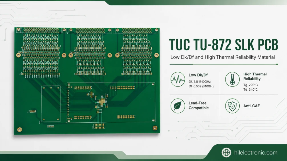
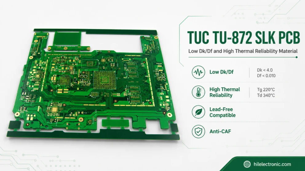
TUC TU-872 SLK occupies a commercially useful middle ground. It is a high-performance modified-epoxy FR-4 system designed for lower Dk/Df than ordinary high-Tg FR-4 while retaining modified-FR-4 process compatibility, strong thermal reliability, moisture resistance, improved z-axis expansion, anti-CAF capability, dimensional stability, and broad construction availability.
TUC identifies the laminate as TU-872 SLK and the matching prepreg as TU-87P SLK. Public typical data include Tg 190°C by TMA, 200°C by DSC, and 220°C by DMA; Td 340°C; 2.3% z-axis expansion from 50–260°C; T260/T288 of 60/20 minutes; and typical Dk 3.8 and Df 0.009 at 10 GHz for a 50% resin-content reference. TUC lists servers, storage, backplanes, line cards, HPC, telecom, base stations, routers, and selected RF applications.
The Middle Ground Between Ordinary FR-4 and Premium Ultra-Low-Loss Materials
A standard high-Tg FR-4 can become loss-limited as route length, frequency, and connector count increase. Moving directly to an ultra-low-loss material may solve the electrical problem but add cost, lead time, limited constructions, unfamiliar processing, and qualification effort. TU-872 SLK is intended to fill the gap: better electrical performance than general-purpose FR-4 without abandoning a familiar modified-epoxy manufacturing base.
| Material tier | Best use | Risk of choosing too low | Risk of choosing too high |
|---|---|---|---|
| General high-Tg FR-4 | Shorter or lower-speed routes where reliability dominates. | Excess insertion loss, smaller eye margin, shorter route limits. | Lowest cost and broadest process base may be lost unnecessarily. |
| TU-872 SLK | Cost-sensitive high-speed multilayers with moderate reach and meaningful reliability needs. | May be insufficient for the longest PAM4 backplanes or multiple-connector channels. | Usually a rational balance if it passes with process guard band. |
| TU-872 SLK Sp / lower-loss TUC family | Longer or more demanding channels within the TUC ecosystem. | Higher cost and possibly narrower process/supply options. | Useful when SLK is close to the limit or roadmap needs more margin. |
| Ultra-low-loss platform material | Longest reaches, highest lane rates, demanding backplanes/chassis interconnects. | Under-design if the channel truly needs the tier. | Over-design if connectors, vias, or short reach dominate. |
The selection should be based on the lowest tier that passes the complete package-to-package channel and reliability requirements. This approach turns high-speed material selection into a cost-controlled engineering decision instead of a brand hierarchy.
Separate Short Server Boards, Line Cards, and Long Backplanes
The word “server” covers very different boards. A compact server motherboard with short CPU-to-device links is not equivalent to a line card with a high-speed connector or a long backplane. TU-872 SLK should be evaluated by route class, not product category.
| Board class | Typical channel pattern | TU-872 SLK decision |
|---|---|---|
| Short server motherboard routes | Short package-to-package paths, limited connector count, dense routing. | Often a strong candidate if loss simulations pass and modified-FR-4 process compatibility is valuable. |
| Storage controller or line card | Moderate routes, BGA breakout, one connector, several vias. | A likely sweet spot; optimize copper, vias, and launch, then verify margin. |
| HPC accelerator board | Mix of short dense routes and selected longer links. | Use route-class limits; SLK may serve most routes while only the longest need another tier. |
| Chassis or midplane card | Longer path, one or more connectors, deeper backdrill. | Model carefully; compare SLK with SLK Sp or an ultra-low-loss family. |
| Long backplane | Multiple board segments/connectors and high PAM4 reach. | SLK may not be sufficient; distributed loss and reflections must be quantified. |
| Base-station/selected RF board | Mixed digital and moderate RF with reliability needs. | Use frequency-specific modeling; do not infer mmWave suitability from “RF” in the application list. |
Layout rules should be tied to these classes. For example, a project can specify a maximum routed length and via count on TU-872 SLK for each lane rate, with a mandatory SI review beyond the limit. This prevents a late layout extension from consuming the material margin without notice.
Build a Cost-versus-Channel-Margin Decision Model
A cost-performance model should include more than laminate price. The lowest-cost board is the one that meets yield, qualification, schedule, and system performance with adequate margin. A premium material may reduce loss but increase panel cost; a cheaper material may require retimers, shorter topology, extra layers, or tighter manufacturing tolerances.
| Cost item | How TU-872 SLK can help | What to quantify |
|---|---|---|
| Material and prepreg | Lower tier than many ultra-low-loss systems. | Price by released construction, MOQ, panel size, regional source, lead time. |
| Fabrication learning | Modified-FR-4 compatibility can reduce process disruption. | Existing factory experience, lamination trials, scrap and qualification effort. |
| Copper and stackup | Dk below 4 can support practical impedance geometry; broad glass/copper availability helps. | Trace width/spacing, VLP foil premium, layer count, panel utilization. |
| System architecture | Adequate channel margin may avoid retimers or topology changes. | Retimer/component cost, power, latency, software and reliability. |
| Yield | Balanced thermal/CAF behavior can improve robust production. | Impedance/loss distribution, bow/twist, hole reliability, rework and scrap. |
| Roadmap | Extra margin may support a future lane rate. | Cost of redesign versus selecting SLK Sp or higher tier now. |
Do not pay for Df that the system cannot use
If connector launches, package loss, or via stubs dominate the channel, reducing laminate Df may recover little system margin. Conversely, if a long straight route dominates, a lower-loss material can be cost-effective. The model should identify the loss contributor before comparing material price.
Use Construction-Specific Electrical Data
The public Dk 3.8 and Df 0.009 values are tied to a stated 50% resin-content condition at 10 GHz. They are useful for family-level comparison but are not universal solver inputs. The actual stackup will use specific cores, prepreg styles, resin contents, cured thicknesses, copper foils, and inner-layer treatments.
| Electrical release item | Required definition |
|---|---|
| Core/prepreg identity | TU-872 SLK core and TU-87P SLK prepreg, exact glass style, resin content, construction and availability. |
| Design Dk/Df | Frequency, test method, construction, and whether the value comes from TUC data, fabricator correlation, or measured coupon. |
| Cured dielectric thickness | Supplier/fabricator pressed-thickness data using actual copper percentages. |
| Copper | Foil profile, base weight, finished thickness, treatment and plating contribution. |
| Impedance geometry | Finished trace top/bottom width, spacing, reference plane, copper and dielectric tolerances. |
| Loss model | Conductor roughness model, dielectric loss, temperature, line geometry, vias and connector launches. |
TUC publishes broad construction availability, but availability should be confirmed for the exact region and factory. A nominally ideal glass style that is not routinely stocked can make the design vulnerable to later substitution. The final stackup should use a construction that the selected fabricator can repeat.
Balance Loss, Moisture, CAF, and Thermal Reliability
TU-872 SLK’s appeal is the combination of electrical and reliability properties. Its modified epoxy system is positioned for moisture resistance, improved z-axis expansion, anti-CAF, thermal stability, and through-hole reliability. These properties matter in high-layer server, storage, telecom, and industrial boards that also need moderate loss.
| Risk | Material contribution | Board/process requirement |
|---|---|---|
| Lead-free reflow | High Tg and thermal resistance support repeated assembly exposure. | Define actual reflow/rework history, moisture state, board temperature and post-process inspection. |
| PTH fatigue | Improved z-axis expansion reduces barrel strain. | Use conservative holes, robust wall copper, controlled drilling/desmear/plating. |
| CAF | Anti-CAF formulation reduces susceptibility. | Maintain voltage spacing, cleanliness, moisture protection and humidity-bias qualification. |
| Moisture | Improved moisture resistance supports environmental stability. | Control storage, bake only when justified, solder mask/coating and enclosure conditions. |
| Dimensional stability | Supports high-layer registration and flatness. | Balance copper, control lamination, panel orientation and bow/twist. |
| Signal loss | Lower Dk/Df than ordinary FR-4 reduces distributed attenuation. | Use construction-specific data, VLP copper where justified, and a complete channel model. |
TU-872 SLK Versus TU-872 SLK Sp
TUC also offers TU-872 SLK Sp. The correct boundary should be based on measured or modeled channel margin, not on a suffix preference. The SLK Sp product page positions it as a lower-loss progression within the family. Because public and member-only data can differ by construction, the project should obtain current controlled data for both candidates from TUC or the fabricator.
| Decision question | Choose TU-872 SLK | Consider TU-872 SLK Sp or lower-loss family |
|---|---|---|
| Does the worst route pass with manufacturing margin? | Yes. | No or only nominally. |
| Is distributed PCB loss the dominant contributor? | Not dominant or adequately controlled. | Yes, after connector/via/topology optimization. |
| Is the platform cost-sensitive and high-volume? | SLK can provide the better commercial balance. | Upgrade if system cost or roadmap benefits exceed material premium. |
| Is the route short but dense? | SLK often sufficient; density and launch design dominate. | Upgrade only if measured evidence shows a need. |
| Does the design need future lane-rate headroom? | Use SLK if redesign is acceptable and current margin is strong. | Use a lower-loss tier if long platform life makes future redesign expensive. |
| Is supply/process maturity critical? | Prefer the construction with proven local availability and yield. | Do not choose a suffix with uncertain construction or factory experience solely for a datasheet number. |
A side-by-side test vehicle should use identical copper, line geometry, launch, via structure, and test method. Otherwise, the measured difference cannot be assigned to the resin/glass system. The comparison should include thermal reliability, CAF, press behavior, availability, and cost as well as insertion loss.
Manufacturing and Inspection Plan
Manufacturing should protect the exact features that make TU-872 SLK a balanced option. If the factory uses a rough inner-layer treatment, uncontrolled prepreg substitution, or an overly tight impedance geometry, the electrical advantage can disappear. If the hole and moisture processes are weak, the reliability advantage can also disappear.
- Incoming control: verify TU-872 SLK/TU-87P SLK construction, glass, resin content, copper, lot and shelf condition.
- Stackup release: calculate pressed thickness from actual copper density; confirm impedance and loss before artwork compensation.
- Lamination: control material temperature, pressure, vacuum, cure, registration, thickness and copper balance.
- Inner-layer treatment: use a qualified adhesion process with acceptable roughness for the channel.
- Etch: measure finished top/bottom width and spacing on representative copper/profile.
- Drilling/desmear/plating: control hole-size-specific parameters, wall copper, annular ring and backdrill.
- Inspection: combine AOI, cross-section, TDR and S-parameter coupons according to route and reliability risk.
- Change control: treat glass, foil, treatment, press, drill, plating and panel-size changes as engineering changes.
Impedance pass is not a loss pass
A TDR coupon can meet impedance while the line has excessive insertion loss from rough copper surfaces or a different Df construction. For the route classes that justify TU-872 SLK, include a transmission-line coupon or other correlated loss test in the first article.
Backdrill and vias
The middle-tier material decision is wasted if residual stubs dominate. Define backdrill side, target residual stub, tolerance, pad clearances, drill wander, and verification. Optimize return vias and reference-plane transitions around every high-speed layer change.
First-Article Evidence for a “Good Enough” High-Speed Material
The first article should prove that the lower-cost tier has enough margin across manufacturing variation. One nominal coupon is not enough to support a “good enough” decision.
| Evidence | Decision supported |
|---|---|
| As-built stackup and copper data | The field-solver geometry matches production. |
| TDR on representative layers | Impedance and localized discontinuities are controlled. |
| Multi-length S-parameter coupon | Distributed loss can be separated from launch loss and compared with the model. |
| Via/backdrill cross-sections | Residual stubs, wall copper, registration and hole quality meet the channel/reliability plan. |
| Panel-position samples | Center/edge thickness and etch variation do not erase margin. |
| Thermal preconditioning | PTH and delamination performance survive the planned assembly history. |
| Humidity/CAF evidence where required | Environmental reliability matches the service condition. |
| System eye/compliance result | The complete package-to-package channel closes with equalization and production guard band. |
The release report should state how much margin remains and which route is limiting. This gives the team a trigger for future changes: a connector substitution, longer route, rougher copper, additional via, or higher lane rate can be evaluated against the documented margin.
RFQ and Approved-Equivalent Rules
| RFQ field | Required content |
|---|---|
| Material | TUC TU-872 SLK core and TU-87P SLK prepreg, exact construction, current TDS, approved alternatives. |
| Application/route classes | Board type, lane rate/modulation, maximum length, connectors, vias, target layers and roadmap. |
| Stackup | Glass/resin content, cores/prepregs, cured thickness, copper foil/profile, finished copper, total thickness. |
| Electrical | Impedance, insertion/return-loss coupon limits, bandwidth, skew/crosstalk where needed, model/data source. |
| Reliability | Lead-free cycles, PTH geometry, CAF/humidity, moisture, IPC/customer class, bow/twist. |
| Process | Lamination, copper balance, inner-layer treatment, etch tolerance, drill/desmear/plating, backdrill and storage. |
| Evidence | CoC, stackup, cross-sections, TDR, S-parameters, thermal/environmental results and lot traceability. |
| Equivalent approval | Same-construction electrical comparison, thermal/CAF/process evidence, availability, price and written engineering approval. |
Final Selection Table
| Project condition | Recommended direction |
|---|---|
| Short/moderate high-speed routes, cost-sensitive high volume, familiar FR-4 factory | TU-872 SLK is a strong candidate. |
| Moderate routes plus high-layer, moisture, CAF and lead-free reliability needs | TU-872 SLK is particularly well aligned. |
| Long multi-connector PAM4 backplane | Compare SLK Sp or an ultra-low-loss family; do not assume SLK passes. |
| Channel failure is caused by via/connector reflection | Fix topology before changing the laminate. |
| Only one public Dk/Df number is available for a different construction | Obtain construction-specific data or build a correlation coupon before release. |
| Product roadmap needs significantly higher lane rate without a board redesign | Price the value of additional margin from SLK Sp or a lower-loss platform. |
| Simple low-speed board | A standard qualified high-Tg FR-4 may be more economical. |
TU-872 SLK’s strongest message is not “high speed.” It is disciplined sufficiency: enough electrical performance, enough thermal and CAF reliability, and enough process compatibility for cost-sensitive multilayers—provided that the worst route and worst reliability structure are verified on the actual construction.
Manufacturer references and release notes
The TUC pages below provide the public basis for the TU-872 SLK material system and the separate SLK Sp option. The approved stackup should use the current controlled core/prepreg data and a project-specific loss correlation rather than treating one 50%-resin comparison number as universal.

Recommended Posts

Taconic RF 35 vs RO4350B PCB
Table of contentsRF-35 vs RO4350B Procurement and...

TMM4 Filter PCB Manufacturing
TMM4 filter PCB manufacturing is controlled by the...

TMM3 PCB Manufacturing for RF Modules
TMM3 PCB manufacturing is most useful where the RF module...

TMM6 PCB Fabrication
TMM6 fabrication is the process-control page for a mid-Dk...
How to get a quote for PCBs
Let’s run DFM/DFA analysis for you and get back to you with a report. You can upload your files securely through our website. We require the following information in order to give you a quote:
-
- Gerber, ODB++, or .pcb, spec.
- BOM list if you require assembly
- Quantity
- Turn time
For PCBA services, please provide your BOM (Bill of Materials) and any specific assembly instructions. We also offer DFM/DFA analysis to optimize your designs for manufacturability and assembly, ensuring a smooth production process.