
ITEQ IT-150GS PCB for High-Layer Reliability
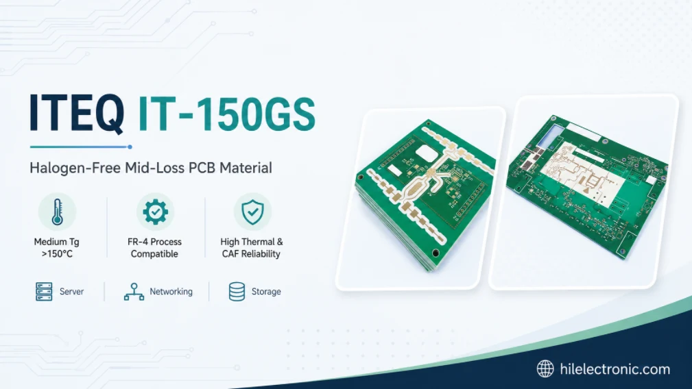
ITEQ IT-150GS is best treated as a reliability-first, halogen-free, mid-loss FR-4 material. It is not the answer to an extreme long-channel loss problem. It is the answer when a multilayer board needs better electrical behavior than standard-loss FR-4 while also facing lead-free thermal exposure, dense plated holes, CAF risk, dimensional control, and cost or availability constraints.
ITEQ’s current product comparison lists typical Dk 3.9 and Df 0.012 at 10 GHz for the stated 50% resin-content reference. That places IT-150GS in a mid-loss class, well above the ultra-low-loss IT-968G and IT-988GSE tiers. The correct engineering question is therefore not “Is the Df low?” but “Does this material and stackup survive the board’s thermal, moisture, voltage, hole, and service stresses while meeting the actual channel budget?”
Why Reliability Can Matter More Than Insertion Loss
Many production failures happen after a signal-integrity simulation has already passed. A barrel crack can open after multiple reflow cycles. Conductive anodic filament growth can create leakage between biased conductors in a humid environment. PCB delamination can occur near copper or a via field. An asymmetric high-layer board can warp enough to disturb assembly. These are material-and-geometry interactions, not merely laminate-property failures.
A mid-loss material can be the correct choice when the route lengths are moderate and the system has adequate electrical margin. In that situation, spending the budget on hole geometry, copper plating, moisture control, thermal profiling, inspection, and robust material qualification often produces more field reliability than moving to an ultra-low-Df resin that the channel does not require.
| Priority | Why it may dominate | Design evidence |
|---|---|---|
| PTH fatigue | Z-axis resin expansion strains the copper barrel, especially in thick boards and small holes. | Aspect ratio, barrel copper, reflow count, cross-sections, thermal cycling or IST plan. |
| CAF resistance | Humidity, bias, ionic contamination, glass/resin interfaces, and conductor spacing interact. | Voltage/spacing map, material CAF capability, cleanliness, drill/desmear, environmental test. |
| Delamination | Moisture, incomplete cure, resin starvation, copper treatment, and thermal shock can separate interfaces. | Material storage, bake rules, lamination profile, microsections, T260/T288 references. |
| Warpage | Copper imbalance, asymmetric stackup, local resin distribution, and assembly temperature distort the panel. | Stackup symmetry, copper balancing, panel tooling, bow/twist limits before and after assembly. |
| Insertion loss | Moderate routes still need a controlled Dk/Df and copper geometry. | Channel simulation with actual construction; confirm that IT-150GS has enough margin. |
Map the Failure Modes Before Selecting the Material
Material selection should begin with a failure map. List the board features and service conditions that can trigger each failure, then assign prevention and verification. This avoids the common practice of using “high Tg” as a proxy for every reliability requirement.
| Failure mode | Board conditions that increase risk | Prevention and verification |
|---|---|---|
| Barrel cracking | Thick board, small finished hole, high aspect ratio, thin or uneven wall copper, multiple reflows, rework, thermal cycling. | Conservative geometry, robust plating, qualified desmear, cross-sections, coupon thermal cycling/IST, controlled assembly profile. |
| Inner-layer separation or pad lift | Poor resin fill, weak oxide/alternative treatment, moisture, thermal shock, excessive press stress. | Resin-flow review, approved treatment, cure control, moisture discipline, thermal-stress testing. |
| CAF growth | Dense biased vias, small spacing, humid service, ionic residues, glass bundles, drilling damage. | Anti-CAF material, spacing/voltage rules, drill/desmear control, cleanliness and humidity-bias qualification. |
| Delamination/blistering | Moisture absorption, incomplete cure, trapped volatiles, incompatible surface, excessive thermal excursion. | Storage/bake plan, vacuum lamination, material-temperature record, microsection and solder-float/reflow qualification. |
| Warpage/twist | Asymmetric copper, mixed copper weights, unbalanced glass, local heavy planes, panel handling. | Symmetric stackup, copper thieving/balance, press plan, panel support, bow/twist measurements. |
| Excessive channel loss | Long routes, narrow traces, rough copper, many vias/connectors. | Loss-budget simulation; use IT-968G/IT-988GSE if distributed loss—not reliability—is the limiting factor. |
High Tg is not a direct reliability guarantee
Tg marks a transition in polymer behavior; it does not by itself specify pre- and post-Tg CTE, total expansion, resin toughness, moisture absorption, adhesion, decomposition behavior, or resistance to repeated strain. A high-Tg material on an aggressive thick-board geometry can still fail, while a well-designed board on a lower-Tg but lower-expansion system can perform well. The board-level stress must be matched to the complete property set and the fabrication process.
Boards That Fit IT-150GS—and Boards That Do Not
IT-150GS is most credible in industrial controls, telecom equipment, storage, servers, automotive electronics, instrumentation, and high-layer PCB assemblies where data rates and reaches are moderate and where halogen-free or enhanced reliability requirements are important. It should not be presented as a universal answer for every product in those categories.
| Product/board type | IT-150GS fit | Why |
|---|---|---|
| Industrial controller with many I/O connectors and plated holes | Strong candidate. | PTH, lead-free, CAF, moisture, and cost may dominate over long-channel loss. |
| Automotive control module with repeated thermal exposure | Candidate subject to automotive qualification. | Thermal cycling, moisture, voltage spacing, and assembly history are central. |
| Telecom control/management board | Strong candidate if routes are moderate. | Needs reliable multilayer processing and may benefit from mid-loss behavior. |
| Server or storage control board with shorter links | Possible fit. | Do not infer from the word “server”; verify route classes and connector count. |
| Long 112G PAM4 backplane | Usually not the first choice. | Distributed channel loss likely requires IT-968G, IT-988GSE, or another lower-loss material. |
| 77 GHz radar antenna layer | Not appropriate as the default. | A frequency-specific mmWave material and antenna validation are needed. |
| Low-cost simple two-layer board | May be over-specified. | A mainstream qualified FR-4 could meet the reliability and electrical needs. |
The selection should identify the reason for using IT-150GS on the drawing. If the reason is halogen-free compliance, specify the applicable limit and certificate. If it is PTH reliability, define the hole geometry and thermal test. If it is mid-loss behavior, release construction-specific SI values and route limits. A material name without the governing requirement is difficult to substitute or audit.
Thick, High-Layer Stackups: Hole and Lamination Risk
High layer count magnifies thermal and mechanical risk. More plies create more registration interfaces, more copper imbalance opportunities, thicker finished boards, longer plated barrels, and greater resin-flow variation. Small holes and deep backdrill may be added at the same time, increasing both fabrication difficulty and stress concentration.
Aspect ratio is a stress multiplier
The barrel of a through hole constrains the expanding resin. As the board gets thicker and the finished hole gets smaller, the copper must survive more strain over a longer unsupported length. The design should avoid selecting the smallest available hole merely to save routing space. Finished-hole tolerance, drill diameter, plating allowance, aspect ratio, annular ring, and minimum wall copper should be reviewed together.
Resin fill and copper balance
IT-150GS prepreg must supply enough resin to fill inner-layer copper topography and via-field density without leaving voids or resin-starved interfaces. Heavy planes next to sparse signal layers can create local thickness and flow differences. The fabricator should perform a resin-demand calculation or equivalent review using actual copper percentages, not only nominal glass-style thickness.
- Use balanced copper distribution where the electrical design allows it.
- Define copper thieving or balancing rules on low-density areas.
- Review resin demand around dense via fields, heavy copper, embedded coins, and large clearances.
- Use sequential lamination only when necessary and qualify the cumulative thermal and registration effects.
- Measure finished dielectric thickness at representative dense and sparse regions during the first article.
- Include edge and center panel locations in registration and thickness sampling.
Drilling and desmear
Drill quality affects both PTH fatigue and CAF. Smear, glass-fiber damage, rough hole walls, nail-heading, and excessive resin recession can compromise the copper interface. Tool life, chip load, entry/backup materials, hit count, stack height, and hole-size-specific parameters should be controlled. Desmear must remove resin without excessively attacking glass or creating a rough interface that traps contamination.
Translate Lead-Free Compatibility Into a Real Thermal History
“Lead-free compatible” does not define the board’s actual thermal history. A product may experience two SMT reflows, selective soldering, wave soldering, connector press-fit, manual touch-up, component replacement, conformal-coating cure, and field rework. The laminate must be evaluated against the cumulative history, while the assembly profile must remain inside component and board limits.
| Thermal event | Distinct board stress | Planning question |
|---|---|---|
| Top-side SMT reflow | First high-temperature excursion; moisture and cure state become visible. | What peak, time above liquidus, heating rate, and board temperature are expected? |
| Bottom-side SMT reflow | Second excursion may occur with different component mass and support. | Does the board remain flat and do plated holes retain margin after the first cycle? |
| Wave solder | Localized but prolonged bottom-side heating and solder contact. | Are through-hole regions, heavy copper, and connectors exposed to a more severe profile? |
| Selective solder | Repeated localized thermal cycles around specific connectors. | Do adjacent vias or copper planes create steep thermal gradients? |
| Rework | Potentially uncontrolled local heating and multiple cycles. | What is the maximum approved rework count and temperature-monitoring method? |
| Field repair | Aged, moisture-exposed board sees another thermal event. | Is bake required and is the repair method qualified for the product class? |
The reliability plan should define a representative preconditioning sequence. Coupons or boards should then be cross-sectioned or electrically tested after the sequence, not only before it. Where risk warrants, interconnect stress testing, thermal cycling, solder-float, or other customer/IPC qualification should be used to verify the actual geometry.
CAF Is a Design-and-Process Problem, Not a Datasheet Checkbox
CAF is the growth of a conductive path along glass/resin interfaces under moisture and electric bias. A laminate advertised as anti-CAF reduces material susceptibility, but design spacing, voltage, hole-wall damage, ionic cleanliness, moisture ingress, and processing remain decisive.
| CAF variable | Risk mechanism | Control |
|---|---|---|
| Voltage and spacing | Higher electric field accelerates migration. | Create a voltage/spacing matrix for vias, pads, traces, planes, and board edges. |
| Humidity and condensation | Moisture enables ionic transport. | Define coating, sealing, drainage, environment, and humidity-bias test as required. |
| Drill damage | Glass/resin separation can create a path. | Control drill condition, desmear, hole-wall quality, and microsection acceptance. |
| Ionic contamination | Residues supply mobile ions. | Control fabrication and assembly cleanliness; test ionic or specific residues when required. |
| Glass architecture | Bundles and interfaces influence path formation. | Use the qualified material construction and do not substitute glass styles casually. |
| Copper features | Dense via fields create strong local fields and many interfaces. | Increase spacing or stagger features where possible; review anti-pad and plane clearances. |
How to Evaluate 370HR, TU-768, and Other High-Tg Alternatives
IT-150GS may be compared with Isola 370HR, TUC TU-768-class products, Shengyi high-Tg FR-4 families, or other reliability-oriented materials. A substitution should not be decided from Tg or brand recognition. The board’s governing failure modes and channel requirements must be compared on the proposed construction.
| Comparison item | Why it matters | Required substitution evidence |
|---|---|---|
| Material identity and compliance | Halogen-free, UL, IPC slash sheet, RoHS/REACH, customer specification may differ. | Current TDS, certificate, UL construction, exact laminate and prepreg designation. |
| Thermal expansion and delamination | Tg alone does not predict barrel strain or interface survival. | Pre/post-Tg CTE, total expansion, Td, T260/T288, thermal-stress data. |
| CAF and moisture | Environmental reliability depends on formulation and process. | CAF test data or qualification history, moisture absorption, cleanliness/process review. |
| Dk/Df and construction | Mid-loss performance can affect route limits and impedance. | Same-frequency/test-method data, resin content, glass style, copper, SI coupon correlation. |
| Prepreg flow and resin fill | A substitute may not fill the same copper topography or cure in the same press cycle. | Flow, gel/cure, pressed thickness, resin-demand review, lamination trial. |
| Fabricator experience and supply | A theoretically similar material can create yield or lead-time risk. | Approved supplier history, stock constructions, panel size, foil options, traceability. |
| Board-level qualification | The final risk is in the built stack, not the datasheet. | Cross-sections, thermal/reflow exposure, PTH/CAF tests, impedance/loss coupons as applicable. |
A downgrade is acceptable when a less expensive material meets all governing requirements with margin and the customer permits it. An upgrade is justified when the existing board geometry or thermal environment exceeds IT-150GS capability, when the longest route needs lower loss, or when a specific compliance/qualification target is unavailable. The change should be documented as a new material-system qualification, not an informal purchasing substitution.
Factory Release Plan and First-Article Evidence
The first article should prove the failure controls identified in the initial map. The evidence package should be tailored: a high-layer connector board needs hole and registration data; a humid high-voltage industrial board needs CAF and cleanliness evidence; a moderate-speed server controller also needs impedance and loss correlation.
- Material records: exact IT-150GS laminate/prepreg, lot, shelf condition, certificate, compliance documents.
- As-built stackup: dielectric/copper thicknesses, glass styles, resin contents, total thickness, copper balance.
- Lamination evidence: press recipe, material temperature, vacuum, cure, registration, resin-fill cross-sections.
- Hole evidence: drill parameters, tool life, desmear, minimum/average wall copper, annular ring, microsections from representative hole sizes.
- Thermal preconditioning: actual or conservative reflow/rework sequence followed by cross-section or electrical verification.
- CAF/cleanliness: process controls and customer-required humidity-bias or cleanliness data.
- Electrical: impedance coupons and, where route length warrants, insertion-loss data on the exact construction.
- Warpage: bow/twist before and after representative assembly exposure for asymmetric or large boards.
Acceptance criteria should be measurable. Replace “good PTH reliability” with minimum wall copper, maximum aspect ratio, approved reflow sequence, crack-free cross-section requirements, and any required cycling result. Replace “anti-CAF” with the applicable test condition or customer standard. This converts marketing language into production control.
Reliability-Focused RFQ
A reliability-focused RFQ should tell the supplier why IT-150GS is being used and which substitutions are prohibited without review.
| RFQ section | What to specify |
|---|---|
| Material system | ITEQ IT-150GS laminate and matching prepreg, exact construction, halogen-free requirement and certificate, current controlled TDS. |
| Board geometry | Layer count, finished thickness, copper weights, smallest finished hole, drill size, aspect ratio, backdrill, via density, heavy copper or local thermal mass. |
| Assembly history | Number of SMT reflows, peak/profile limits, wave/selective solder, expected rework, bake/handling requirements. |
| Reliability class | IPC class/customer standard, PTH test, CAF/environmental requirements, cleanliness, moisture protection, operating temperature. |
| Electrical | Impedance targets, moderate high-speed route classes, construction-specific Dk/Df source, coupon plan. |
| Process controls | Lamination, resin-fill review, copper balance, drilling, desmear, plating, inner-layer treatment, registration, bow/twist. |
| Evidence | CoC, stackup report, press record, cross-sections, plating data, thermal preconditioning, electrical coupons, lot traceability. |
| Substitution | No generic high-Tg replacement; require property matrix, process trial, board-level test, availability review, and written approval. |
The RFQ should also state which parameters may be optimized by the fabricator. For example, the supplier may propose a different glass-style combination to meet thickness and resin-fill needs, but the proposal should be approved before impedance artwork and qualification are frozen.
Practical Questions From Design, Quality, and Procurement
Can IT-150GS replace 370HR or TU-768?
Possibly, but not automatically. Compare exact grade, halogen-free status, slash sheet/UL construction, thermal expansion, T260/T288, moisture/CAF, prepreg behavior, Dk/Df, availability, and the board-level qualification. A matching Tg is not enough.
How many reflow cycles can it survive?
There is no universal count independent of board geometry and profile. Use the planned thermal history, hole geometry, moisture condition, plating, and acceptance test. A material can be lead-free compatible while an aggressive thick-board build still has insufficient margin.
What is the most important high-layer control?
There is no single control, but the combination of conservative hole geometry, uniform plating, controlled resin fill, copper balance, and measured thermal history is usually more important than selecting the highest Tg number.
Can it be used for high-speed links?
Yes for routes whose modeled loss budget fits a mid-loss Df construction. It should not be assumed suitable for long 56G/112G PAM4 channels without simulation and coupon correlation.
When should the design upgrade?
Upgrade when the complete channel is loss-limited after topology optimization, when the thermal/interconnect stress exceeds the qualified IT-150GS construction, or when a specific compliance or customer qualification requires another grade.
The most defensible IT-150GS article is therefore a reliability decision document: it names the likely failure, shows how the stackup and process prevent it, identifies the evidence required at first article, and defines when a lower- or higher-tier substitute is acceptable.
Manufacturer references and release notes
The public ITEQ references below support the material-family positioning and the comparison values quoted in this guide. Because detailed thermal data, constructions, and regional supply can be revision-dependent, the quotation package should include the current controlled IT-150GS datasheet and matching prepreg confirmation.

Recommended Posts

Taconic RF 35 vs RO4350B PCB
Table of contentsRF-35 vs RO4350B Procurement and...

TMM4 Filter PCB Manufacturing
TMM4 filter PCB manufacturing is controlled by the...

TMM3 PCB Manufacturing for RF Modules
TMM3 PCB manufacturing is most useful where the RF module...

TMM6 PCB Fabrication
TMM6 fabrication is the process-control page for a mid-Dk...
How to get a quote for PCBs
Let’s run DFM/DFA analysis for you and get back to you with a report. You can upload your files securely through our website. We require the following information in order to give you a quote:
-
- Gerber, ODB++, or .pcb, spec.
- BOM list if you require assembly
- Quantity
- Turn time
For PCBA services, please provide your BOM (Bill of Materials) and any specific assembly instructions. We also offer DFM/DFA analysis to optimize your designs for manufacturability and assembly, ensuring a smooth production process.