
Back to blog
Mastering PCB Design: Strategies, Guidelines & Best Practices

PCB Schematic Diagram–PCB Design
PCB is analogous to the skeleton and nervous system of electronic circuits, playing a pivotal role in electronic engineering projects. However, many individuals lack understanding or possess insufficient knowledge regarding PCB design.
During my university years, I developed a particular interest in circuit board and hardware circuit design, and I studied these subjects diligently. At the time, I believed that securing a job involving computer-aided design (CAD) in an office setting after graduation would be ideal. After graduating, I successfully landed a position at an electronic company in Guangzhou, where I worked as a PCB engineer. Initially, I had to be well-versed in various tasks, including schematic drawing, component selection, PCB layout, prototype soldering, debugging, bill of materials (BOM) creation, and work instruction preparation. This experience marked the beginning of my journey in the electronics industry.
The Crucial Role of Schematic Diagrams in PCB Design
While a good schematic diagram cannot guarantee good routing, quality routing begins with a good schematic. When creating a schematic, thorough consideration is required, with careful attention to the signal flow of the entire circuit. A smooth and steady signal flow from left to right in the schematic should translate to a similarly good signal flow on the PCB. It is advisable to provide as much useful information as possible in the schematic.
At times, when circuit design engineers are unavailable, customers may request our assistance in solving circuit issues. Designers, technicians, and engineers engaged in this work are often appreciative, as are we. In addition to common information such as reference designators, power consumption, and tolerance, what other information should be included in the schematic? The following suggestions can elevate an ordinary schematic to a top-notch one: include waveforms, mechanical information regarding the housing, printed line lengths, blank areas; indicate which components should be placed on the PCB; provide adjustment information, component value ranges, heat dissipation information, controlled impedance printed lines, annotations, concise circuit action descriptions, and more.
Guidelines for Effective Collaboration in PCB Design
If you did not design the routing yourself, it is essential to allocate ample time to meticulously review the routing designer’s work. At this juncture, a small precaution can outweigh a hundred remedies. Do not presume that the routing individual can grasp your ideas. Your opinions and guidance are most crucial in the initial stages of the routing design process. The more information you provide and the more involved you are throughout the routing process, the better the resulting PCB will be. Establishing a provisional completion point for the routing designer—rapidly reviewing the progress of the routing according to your desired routing—can prevent the routing from straying off course, thus minimizing the likelihood of rework.
Instructions for the routing engineer should include: a brief description of the circuit function, a PCB schematic indicating the locations of inputs and outputs, PCB stack-up information (e.g., board thickness, number of layers, detailed information on each signal layer and ground plane—power, ground, analog signal, digital signal, and RF signal); which signals each layer requires; placement requirements for critical components; exact locations of bypass components; which printed lines are critical; which lines require controlled impedance printing; which lines require matched lengths; component dimensions; which printed lines need to be kept apart (or close together); which lines need to be kept apart (or close together); which components need to be kept apart (or close together); which components need to be placed on top of the PCB and which need to be placed underneath. Never complain about providing too much information to others—Is it too little? Yes; Is it too much? No.
Learning from Mistakes: The Importance of Component Placement in Complex PCB Designs
About 10 years ago, I designed a multi-layer surface-mount circuit board—both sides of the board had components. The board was secured in a gold-plated aluminum housing with many screws (due to very strict shock resistance requirements). Pins for bias feeding were provided through the board. This was a very complex device. Some components on the board were used for setting (SAT) testing. However, I had clearly specified the locations of these components. Can you guess where these components were all installed? That’s right, they were installed on the bottom of the board. When the product engineer and technician had to disassemble the entire device, complete the setting, and then reassemble it, they were not pleased. I have not made that mistake again since then.
Enhancing PCB Efficiency through Strategic Circuit Layout
Just as in PCBs, position determines everything. Where a circuit is placed on a PCB, where its specific circuit elements are installed, and what other circuits are adjacent to it are all crucial.
Usually, the positions of inputs, outputs, and power supplies are predetermined, but the circuits between them require some “creativity”. That’s why paying attention to routing details will yield significant returns. Starting from the position of key components, consider the specific circuit and the entire PCB. Specifying the positions of key components and the signal paths from the beginning helps ensure that the design achieves the expected operational goals. Getting the design right the first time can reduce costs and stress—and shorten the development cycle.
Additionally, let’s discuss those “special pads” on the PCB:
First, teardrop pad The teardrop is a drop connection between a pad and a conductor or between a conductor and a via. The purpose of setting the teardrop is to prevent the contact point between the conductor and the pad or the conductor and the via from disconnecting when the circuit board is subjected to a huge external force, and also to make the PCB circuit board look more beautiful. The function of the teardrop is to prevent the signal line width from suddenly narrowing, which can make the connection between the routing and the component pad smoother and solve the problem of easy breakage of the connection between the pad and the routing.
- On welding, it can protect the pad and prevent the pad from falling off during multiple welds.
- Enhance the reliability of the connection (to avoid cracks caused by uneven etching and offset of vias in production)
- Smooth impedance, reduce the sharp change of impedance In PCB design, in order to make the pad more robust and prevent the pad from disconnecting from the conductor during mechanical board making, a transition zone is often arranged between the pad and the conductor, shaped like a teardrop, hence often called a teardrop (Teardrops).
Second, discharge tooth This thing is called a discharge tooth, discharge gap, or spark gap. The spark gap is a pair of triangles with sharp angles pointing towards each other, with the tips of the triangles spaced from a maximum of 10 mils to a minimum of 6 mils. One triangle is grounded, and the other is connected to the signal line. This triangle is not a component but is made of copper foil layers used in the PCB routing process. These triangles need to be placed on the top layer (component side) of the PCB and cannot be covered by solder resist.
- During surge testing of switching power supplies or ESD testing, high voltage will be generated at both ends of the common mode inductor, causing arcing. If the distance to surrounding components is close, it may damage the surrounding components. Therefore, a discharge tube or varistor can be connected in parallel at its two ends to limit its voltage and thus play a role in extinguishing the arc. Although placing a surge protector is effective, it is relatively expensive.
- Another way is to add a discharge tooth at both ends of the common mode inductor in the PCB design, so that the inductor discharges through the two pointed ends of the discharge tooth, avoiding discharge through other paths, thus minimizing the impact on surrounding and subsequent-stage components.
Discharge gaps do not require additional costs, just draw them on the PCB when drawing the board, but it is important to note that this form of discharge gap is an air-form discharge gap and can only be used in environments where ESD occurs occasionally. If used in environments where ESD occurs frequently, carbon deposits will accumulate at the two points of the triangle due to frequent discharge, eventually causing a short circuit on the discharge gap and causing a permanent short circuit of the signal line to the ground, resulting in a system failure.
In fact, there are many joys in PCB design, but only by practicing will you have a deep understanding. If friends have any feelings about PCB design after reading this article, they can contact us for exchange.
For production planning, it also helps to compare this topic with PCB material selection and surface finish comparison before finalizing the fabrication or assembly package.
Conclusion
PCB design is crucial in electronics, forming the circuit’s core. Yet, understanding is often limited. Thorough schematics, detailing waveforms, mechanics, and placements, underpin quality routing. Rigorous review, clear communication, and early path/component specification prevent issues, ensure satisfaction, and optimize efficiency. Specialized pads (teardrops, discharge teeth) boost reliability by preventing detachment and mitigating high voltage. Experience and knowledge-sharing are key to mastering PCB design.
PCB & PCBA Quick Quote
Related Articles
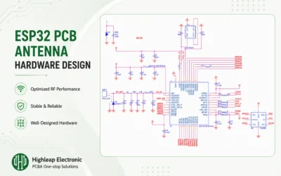
ESP32 PCB Antenna Hardware Design Guide
Last updated: May 2026 · An RF hardware-design guide for ESP32-WROOM integrations Getting good Wi-Fi and Bluetooth range out of an ESP32 design is less abo
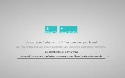
Gerber Viewer: Check PCB Files Before Fabrication
Last updated: May 2026 · A practical guide to viewing and verifying Gerber data A Gerber viewer is a tool that renders the Gerber and drill files exported
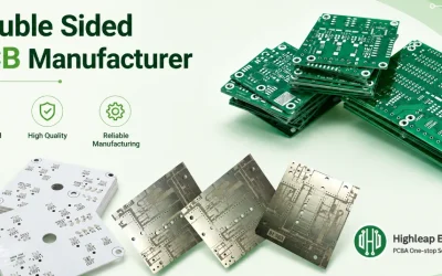
Double-Sided PCB Manufacturer Selection Guide
Last updated: May 2026 · A buyer’s and designer’s guide to 2-layer printed circuit boards A double-sided PCB (also called a 2-layer board) has copper on bo