
Back to blog
Fundamentals of Rectifier Diodes in Electronics

Application of Rectifier Diodes in Inverter
In the realm of electronics, rectifier diodes are unassuming yet crucial components that play a pivotal role in converting alternating current (AC) into direct current (DC). Their ability to facilitate one-way electrical flow is fundamental to the operation of countless electronic devices, from power supplies to consumer electronics. This comprehensive guide explores the intricacies of rectifier diodes, detailing their function, applications, and essential considerations for engineers and enthusiasts alike.
Introduction to Rectifier Diodes
Rectifier diodes, often simply referred to as rectifiers, are semiconductor devices designed to rectify AC voltage into DC voltage. Think of them as electrical valves that permit current flow in one direction while blocking it in the opposite direction. This functionality is crucial for transforming the erratic oscillations of AC electricity into the steady flow required by electronic devices.
Key Characteristics and Construction
Rectifier diodes are predominantly made from silicon due to its favorable electrical properties, although materials like gallium arsenide and germanium are occasionally used in specialized applications. The physical structure of a rectifier diode typically consists of:
- Anode and Cathode: The two terminals of the diode through which current flows. Current enters through the anode (+) and exits through the cathode (-).
- P-N Junction: The interface between the P-type and N-type semiconductor materials within the diode, which controls the flow of current based on the applied voltage polarity.
- Symbol Representation: In circuit diagrams, rectifier diodes are depicted by a triangle with a line at the tip pointing towards the cathode, indicating the direction of current flow under forward bias.
Working Principle of Rectifier Diodes
The working principle of rectifier diodes revolves around their ability to convert alternating current (AC) into direct current (DC) by allowing current flow in one direction while blocking it in the reverse direction. This capability is crucial for their application in various electronic circuits, where stable DC voltage is required. Rectifier diodes achieve this through two main rectification methods: half-wave rectification and full-wave rectification.
Half-Wave Rectification
In a half-wave rectifier circuit, a single rectifier diode is utilized to convert AC voltage into DC voltage. Here’s how it operates:
- AC Input: The circuit begins with an alternating current (AC) source, typically delivering a sinusoidal waveform with alternating positive and negative half-cycles.
- Diode Conduction (Positive Half-Cycle): During the positive half-cycle of the AC waveform, the diode becomes forward-biased. This means the anode of the diode is positive relative to the cathode, allowing current to flow through the circuit and the load connected to it.
- Blocking (Negative Half-Cycle): Conversely, during the negative half-cycle of the AC waveform, the diode becomes reverse-biased. In this state, the anode of the diode is negative relative to the cathode, which blocks any current flow through the circuit. As a result, no output voltage is observed across the load during this period.
- Output: The output of a half-wave rectifier is characterized by a pulsating DC voltage. It only utilizes one half of the AC input waveform, resulting in a less smooth output compared to full-wave rectification.
Full-Wave Rectification
Full-wave rectification utilizes a bridge rectifier configuration consisting of four rectifier diodes arranged in a bridge circuit. This method improves upon the efficiency and smoothness of the output compared to half-wave rectification:
- AC Input: Similar to half-wave rectification, the circuit starts with an AC source providing a sinusoidal waveform.
- Bridge Rectifier Configuration: The four diodes in the bridge rectifier are arranged in such a way that during each half-cycle of the AC input, two diodes conduct current. This setup allows current to flow through the load in the same direction during both the positive and negative halves of the AC cycle.
- Output: As a result of the bridge rectifier configuration, the output across the load is a significantly smoother DC voltage with reduced ripple compared to half-wave rectification. This smoother output is achieved because the bridge rectifier utilizes both halves of the AC waveform, effectively doubling the frequency of the rectified signal.
Rectifier diodes are fundamental components in electronics, enabling the conversion of AC voltage into DC voltage through half-wave and full-wave rectification methods. While half-wave rectification is simpler and uses fewer components, full-wave rectification offers improved efficiency and a smoother DC output suitable for many electronic applications. Understanding these principles is essential for engineers and hobbyists alike to design and implement effective power supply circuits for various electronic devices and systems.

Half-Wave Rectification and Full-Wave Rectification
Applications of Rectifier Diodes
Rectifier diodes are versatile components widely used across various industries and applications due to their ability to convert alternating current (AC) to direct current (DC) efficiently. Here are some key applications where rectifier diodes play a crucial role:
1. Power Supplies: Rectifier diodes are fundamental in power supply units (PSUs) for converting AC voltage from mains electricity into stable DC voltage. This is essential for powering electronic devices ranging from small gadgets like smartphones and laptops to larger appliances and industrial equipment.
2. Battery Chargers: In charging circuits, rectifier diodes convert AC from the mains into DC suitable for charging batteries. This application is critical in portable electronics, automotive battery chargers, and uninterruptible power supplies (UPS).
3. Rectifier Bridges: Industrial power supplies and motor drives often use rectifier diode bridges, which consist of four diodes in a bridge configuration. These bridges rectify AC voltage efficiently and reliably, making them indispensable in industrial automation and large-scale electrical systems.
4. Consumer Electronics: Rectifier diodes are integral components in a wide range of consumer electronics such as televisions, home audio systems, and HVAC (heating, ventilation, and air conditioning) units. They ensure a stable DC voltage supply for critical components, enabling these devices to function reliably.
5. HVAC Systems: Heating, ventilation, and air conditioning systems utilize rectifier diodes for rectifying AC power in control circuitry and motor drives. This application ensures efficient operation and control of HVAC equipment in both residential and commercial settings.
6. Cathode Ray Tube (CRT) Displays: Older CRT monitors and televisions require rectifier diodes to convert AC voltage into the DC voltage needed to power the electron gun and display operation. While CRT technology is less common today, rectifier diodes remain essential for these legacy devices.
7. Variable Frequency Drives (VFDs): In industrial settings, VFDs use rectifier diodes to convert AC power to DC before converting it back to variable-frequency AC to control motor speed and torque. This application is crucial in industries requiring precise control over motor operations.
8. Photovoltaic (PV) Systems: Rectifier diodes are employed in solar photovoltaic systems to convert DC power generated by solar panels into usable AC or DC power for household or grid applications. These diodes prevent reverse current flow and ensure efficient energy conversion.
9. Telecommunications: Rectifier diodes are used in telecommunications equipment and network infrastructure to convert AC mains power into stable DC voltage for reliable operation of communication devices, routers, and servers.
10. Medical Equipment: In medical devices and equipment, rectifier diodes play a critical role in converting AC power to DC for various applications such as patient monitoring systems, diagnostic equipment, and surgical instruments.
The applications of rectifier diodes span across numerous industries and technological domains, underpinning the efficient conversion and control of electrical power. Their reliability, efficiency, and ability to convert AC to DC make rectifier diodes essential components in modern electronics, industrial automation, renewable energy systems, and consumer products. Understanding these applications underscores the importance of rectifier diodes in enabling the functionality and performance of diverse electronic and electrical systems.
Suggestions from PCB Assembly Technicians on Rectifier Diodes
As a PCB assembly engineer, here are some suggestions regarding PCB design for Rectifier Diode:
- Heat Dissipation Considerations: Rectifier diodes generate heat during operation. Therefore, ensure the PCB design provides adequate heat dissipation. This can be achieved by allocating sufficient copper area for heat dissipation in the PCB layout or by adding heatsinks or thermal management components where necessary.
- Current Carrying Capacity: Ensure the PCB layout and traces are sufficiently wide to handle the maximum rated current of the rectifier diodes. Proper trace width and copper thickness can reduce resistive losses during current flow and ensure stable current transmission.
- Voltage Tolerance: Consider the voltage tolerance of rectifier diodes in both forward and reverse working conditions. In PCB design, ensure sufficient spacing and insulation to prevent electrical breakdown or arcing, especially in high-voltage applications.
- Optimized Layout: During PCB layout, place rectifier diodes and related components strategically to minimize electromagnetic interference (EMI) and crosstalk in the circuit. Optimizing the layout also simplifies the assembly process and enhances overall circuit reliability and stability.
- Marking and Indication: Clearly label the polarity and part number of rectifier diodes on the silkscreen layer of the PCB. This helps assembly engineers to correctly identify and install rectifier diodes, avoiding reverse installation or component mismatches.
- Quality Control: During PCB manufacturing and assembly, strict control of process parameters and quality standards is essential. Ensure PCB reliability to prevent rectifier diode failures or damage due to assembly defects or material issues.
- Testing and Validation: After PCB assembly, testing and validating the rectifier diodes are necessary steps. Use appropriate testing equipment (such as a digital multimeter) to check the forward and reverse operational characteristics of each rectifier diode to confirm proper functioning and compliance with design requirements.
Testing Rectifier Diodes
Rectifier diodes can be tested using a digital multimeter (DMM) to ensure they are functioning correctly under both forward and reverse bias conditions. Here’s a step-by-step guide on how to test rectifier diodes:
- Forward Bias Test:
- Turn off the circuit for safety.
- Set the digital multimeter to the diode test mode (often indicated by a diode symbol or a sound wave symbol).
- Identify the anode and cathode terminals of the diode. Refer to the datasheet or look for markings (e.g., a band or line) on the diode.
- Connect the black (negative) lead of the multimeter to the cathode (negative) terminal of the diode.
- Connect the red (positive) lead of the multimeter to the anode (positive) terminal of the diode.
- The multimeter should display a voltage drop of approximately 0.5 to 0.7 volts, indicating that the diode is conducting in forward bias mode.
- Reverse the leads and ensure that the multimeter displays “OL” (open loop), indicating high resistance and no current flow, which is expected in reverse bias mode.
- Reverse Bias Test:
- Keep the circuit powered off.
- Repeat the setup with the multimeter leads reversed: connect the red lead to the cathode and the black lead to the anode of the diode.
- The multimeter should display “OL” or a high resistance value, indicating that the diode is blocking current flow in reverse bias mode.
- Verify that reversing the multimeter leads again shows a forward bias condition with a voltage drop around 0.5 to 0.7 volts.
- Behavior and Interpretation:
- Observe the behavior of the diode during testing. A good diode will conduct significantly in forward bias and block current effectively in reverse bias.
- If the diode fails to conduct properly in forward bias (no voltage drop) or does not block current in reverse bias (low resistance or continuity), it may be defective and should be replaced.
Conclusion
Rectifier diodes are indispensable components in modern electronics, facilitating the conversion of AC to DC voltage with efficiency and reliability. Understanding their operational principles, types of rectification, applications, and testing methodologies is essential for engineers and enthusiasts working in electronics, power systems, and industrial automation. As technology advances, rectifier diodes continue to play a crucial role in enabling efficient energy conversion and powering a wide array of electronic devices and systems.
FAQs
-
What is the impact of junction capacitance in rectifier diodes?
Junction capacitance in rectifier diodes can affect high-frequency performance and switching characteristics. It’s crucial in applications requiring fast recovery times and minimal switching losses. Engineers often consider it when designing circuits for optimal performance in radio frequency (RF) and switching power supplies.
-
How do temperature variations affect the performance of rectifier diodes?
Temperature changes can significantly alter the forward voltage drop and leakage currents of rectifier diodes. This thermal dependency is critical in applications exposed to varying environmental conditions, influencing circuit stability and efficiency over operational ranges. Thermal management techniques such as heatsinks and thermal pads mitigate these effects.
-
Can rectifier diodes exhibit reverse recovery effects?
Yes, rectifier diodes can exhibit reverse recovery effects when transitioning from forward conduction to reverse blocking. This phenomenon, characterized by a temporary current spike during the switching transition, is important in fast-switching circuits like motor drives and pulse-width modulation (PWM) controllers. Choosing diodes with low reverse recovery time (trr) minimizes these effects.
-
What role do snubber circuits play in rectifier diode applications?
Snubber circuits, often consisting of resistors and capacitors, are used across rectifier diodes to dampen transient voltage spikes and ringing caused by inductive loads or switching operations. They improve reliability by reducing stress on diodes and other components, enhancing overall circuit longevity in industrial and power electronics applications.
-
How does junction temperature affect the reliability of rectifier diodes?
Junction temperature directly impacts the MTBF (Mean Time Between Failures) of rectifier diodes. Excessive heat accelerates wear-out mechanisms, potentially leading to premature failures. Design considerations include thermal management strategies like proper heat sinking, airflow optimization, and derating current ratings to ensure reliable long-term operation.

Recommended Posts

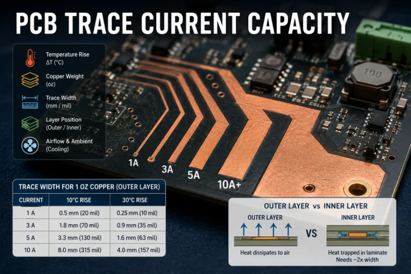
PCB Current Calculator: Sizing Trace Width and Vias with the IPC-2221 Formula
Figure 1. Pcb Current Calculator reference image for PCB...
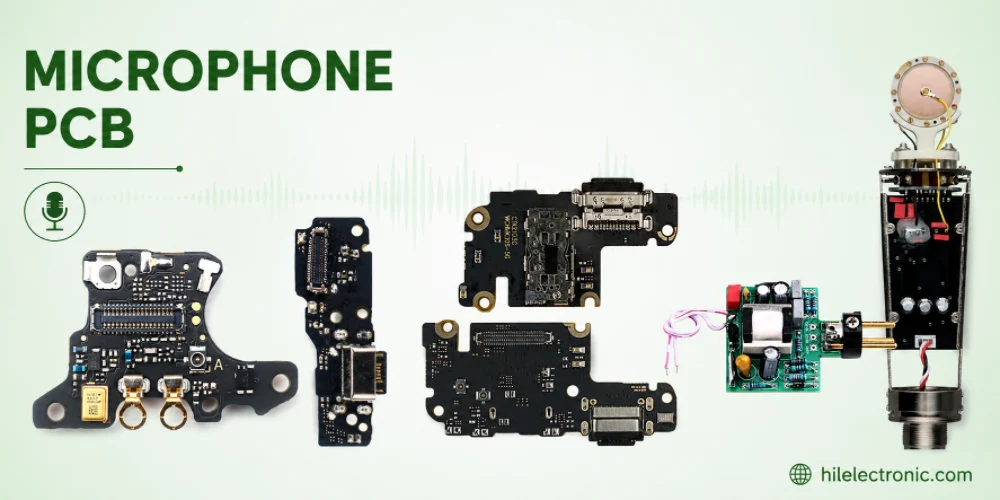
Microphone PCB Design: How the Board Itself Shapes Your Audio Quality
Figure 1. Microphone Pcb reference image for PCB...
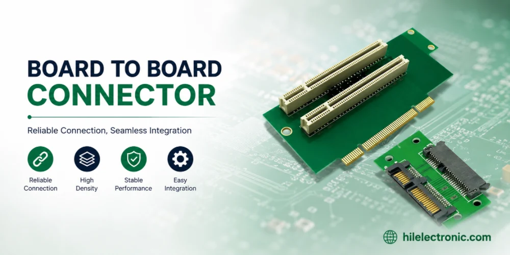
Board-to-Board Connector: Types, Specifications, and How to Select One
Figure 1. Board To Board Connector reference image for PCB...
PCB Trace Width Calculator: How to Size Traces for Current, Voltage Drop, and Impedance
Figure 1. A PCB trace width calculator is a starting point...
Take a Quick Quote