
Thermal Conductivity in MCPCB | Understanding the Real Performance Bottlenecks

Introduction
MCPCB thermal performance depends not only on metal substrate conductivity but also on insulation thickness and interfacial thermal resistance. While many designers focus primarily on selecting aluminum or copper substrates with high thermal conductivity values, they often overlook the critical bottlenecks that truly determine heat transfer efficiency. In high-power applications like LED modules where aluminum PCB heat transfer is essential, understanding these limiting factors becomes crucial for achieving optimal thermal management.
Understanding Thermal Conductivity in MCPCB Systems
The Heat Transfer Path
The thermal conduction path in MCPCBs follows a predictable route: heat flows from the copper circuit layer through the dielectric insulation layer and finally into the metal base substrate. While aluminum offers approximately 200 W/m·K thermal conductivity and copper reaches 400 W/m·K, these impressive figures only tell part of the story.
The actual temperature rise in your components often bears little correlation to these theoretical values. In practical MCPCB thermal performance, the dielectric layer becomes the dominant factor that defines overall thermal resistance. This reality forces us to reconsider our approach to thermal design, shifting focus from substrate selection to understanding the complete thermal stack.

Typical heat flow path and layer structure explaining thermal conductivity in MCPCB
Thermal Conductivity in MCPCB: The Dielectric Bottleneck
Critical Layer Analysis
The dielectric layer presents the most significant thermal barrier in any MCPCB design. With thermal conductivity typically ranging from 0.8 to 3 W/m·K, this insulation layer conducts heat roughly 100 times worse than the aluminum substrate beneath it. When dielectric thickness increases from 50 μm to 100 μm, the thermal resistance nearly doubles, following the basic relationship R = t/(k × A).
Practical Impact on Performance
Consider this practical impact: a high-performance MCPCB with 3 W/m·K dielectric at 75 μm thickness creates more thermal resistance than 5mm of aluminum substrate. Even premium aluminum alloys with superior thermal properties cannot compensate for a poorly specified dielectric layer.
Reducing dielectric thickness or using higher-conductivity materials directly improves aluminum PCB heat transfer efficiency. This fundamental principle guides effective thermal conductivity in MCPCB optimization, yet remains underappreciated in many design specifications.
Interfacial Thermal Resistance in MCPCB Structures
The Hidden Barrier
Interface thermal resistance emerges at every material boundary within the MCPCB structure. Microscopic air gaps, surface roughness, and oxidation layers at the copper-dielectric and dielectric-aluminum interfaces create additional thermal barriers. These interfaces can contribute 20-40% of total thermal resistance, yet remain invisible in standard thermal conductivity specifications.
Manufacturing Impact on Thermal Conductivity
Manufacturing process control significantly impacts interfacial resistance in MCPCB thermal performance. Lamination pressure, curing uniformity, and surface preparation all influence the quality of thermal contact between layers. Advanced manufacturers employ specialized treatments and high-thermal-conductivity adhesives to minimize these interface effects.
Even with excellent aluminum PCB heat transfer capacity, poor interfacial bonding can significantly degrade overall thermal conductivity in MCPCB assemblies. This manufacturing variability explains why identical designs from different suppliers often show substantially different thermal performance.
Quantitative Analysis of MCPCB Thermal Conductivity
Breaking Down Thermal Resistance
The total thermal resistance in an MCPCB follows a series model where each layer adds to the overall resistance. Understanding this distribution is essential for optimizing thermal conductivity in MCPCB designs. A typical thermal resistance breakdown reveals surprising proportions:
- R_Dielectric typically accounts for 50-70% of total thermal resistance
- R_Interface contributes 20-30% of the total
- R_Metal_Base represents only 5-15% despite its high conductivity
Optimization Priorities
This distribution clearly indicates where optimization efforts yield the greatest returns for MCPCB thermal performance. Switching from standard aluminum to copper substrate might reduce total thermal resistance by 5%, while improving dielectric thermal conductivity from 1 to 3 W/m·K can reduce it by 40%.
The message is clear: improving the dielectric and interface layers provides the greatest impact on overall thermal resistance. This insight fundamentally changes how we approach thermal conductivity in MCPCB design optimization.

Metal Core PCB Structure
Real-World Thermal Conductivity in MCPCB Applications
Laboratory Testing Results
Laboratory testing of identical aluminum substrates with varying dielectric specifications demonstrates these principles dramatically. Two MCPCBs with the same 1.6mm aluminum base but different dielectric layers showed remarkable performance differences. The first, with 50 μm thickness at 2 W/m·K conductivity, vastly outperformed the second with 100 μm at 1 W/m·K conductivity.
The thinner, higher-conductivity dielectric configuration achieved junction temperatures 15°C lower under identical 10W power loads. This 3.5x difference in thermal resistance occurred despite using identical aluminum substrates, proving that substrate selection alone doesn’t determine MCPCB thermal performance.
Interface Quality Effects
Another revealing comparison involved surface preparation techniques affecting thermal conductivity in MCPCB assemblies. Identical MCPCB stackups processed with standard versus optimized lamination showed 25% thermal resistance variation solely due to interfacial quality differences.
These real-world observations confirm that theoretical conductivity values alone cannot predict actual thermal performance. The combined effects of dielectric properties and interface quality determine the true thermal conductivity in MCPCB systems more than any single material property.
Optimizing Thermal Conductivity in MCPCB Design
Practical Guidelines for Engineers
Effective thermal management requires balancing multiple factors beyond substrate selection to achieve optimal MCPCB thermal performance. Start by specifying the thinnest dielectric layer that meets your electrical isolation requirements—every 10 μm reduction can improve thermal performance by 15-20%.
Select dielectric materials with thermal conductivity above 2 W/m·K when possible, even if this increases material costs. The performance gains typically justify the investment in applications where thermal conductivity in MCPCB systems is critical.
Interface Optimization Strategies
Interface optimization demands attention during both design and manufacturing phases to maximize aluminum PCB heat transfer. Specify appropriate surface finishes and work with manufacturers who understand thermal interface management. Request thermal resistance measurements rather than relying solely on material property datasheets.
Consider implementing thermal vias where appropriate, as these can bypass the dielectric layer entirely for localized hot spots. However, remember that via effectiveness depends on proper filling and thermal connection, reinforcing the importance of manufacturing quality in achieving optimal thermal conductivity in MCPCB assemblies.
Conclusion
Understanding these limiting factors is essential for accurately evaluating MCPCB thermal performance and optimizing aluminum PCB heat transfer in real-world applications. The dielectric layer and interfacial resistance, not the metal substrate, determine the true thermal performance ceiling of your design.
By focusing optimization efforts on these critical bottlenecks, engineers can achieve substantial improvements in thermal management without the cost premium of exotic substrate materials. Success in thermal conductivity in MCPCB optimization requires viewing the entire thermal stack as a system rather than focusing on individual material properties.
At Highleap Electronics, we specialize in MCPCB manufacturing with optimized thermal performance through careful control of dielectric specifications and interface quality. Contact our engineering team to discuss how proper thermal design can enhance your high-power applications.

Recommended Posts
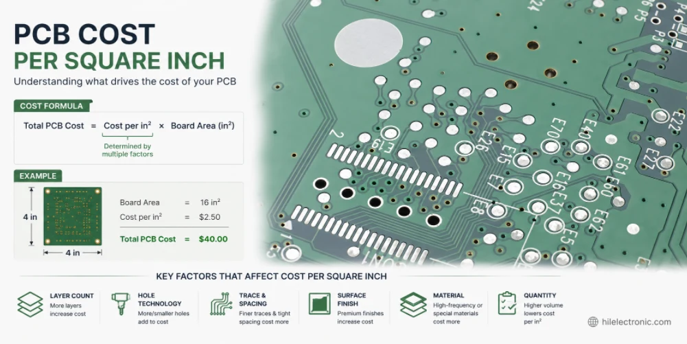
PCB Cost Per Square Inch: What Drives PCB Price and How to Reduce It
Figure 1. PCB cost per square inch image for PCB...
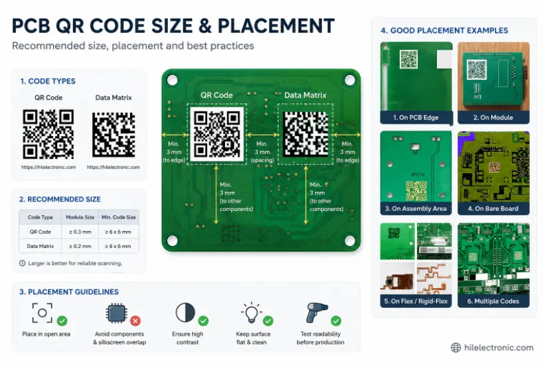
PCB QR Code Size and Placement: Design Rules for Reliable Scanning
Figure 1. PCB QR code size and placement image for PCB...
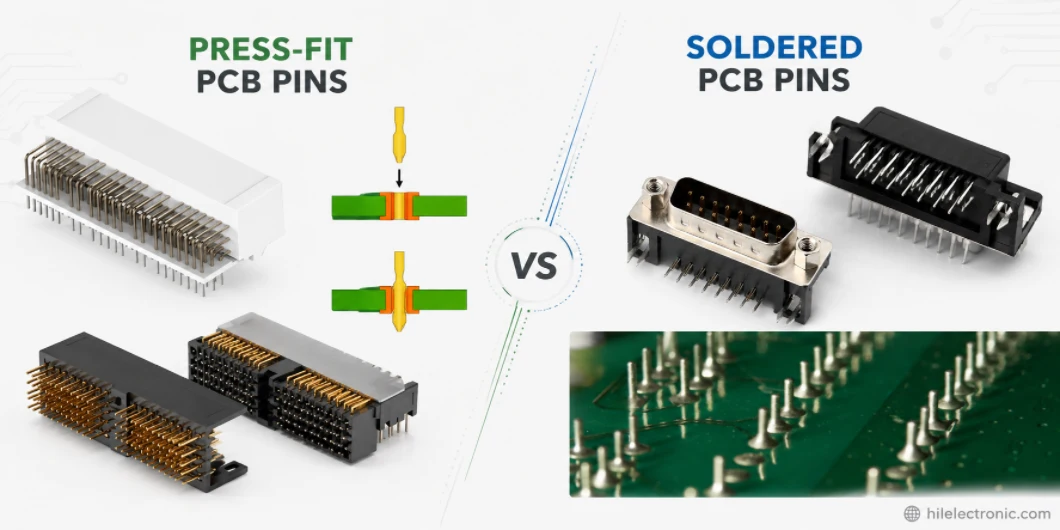
Press-Fit vs Soldered PCB Pins: Header, Connector, and Through-Hole Choices
Figure 1. press-fit vs soldered PCB pins image for PCB...
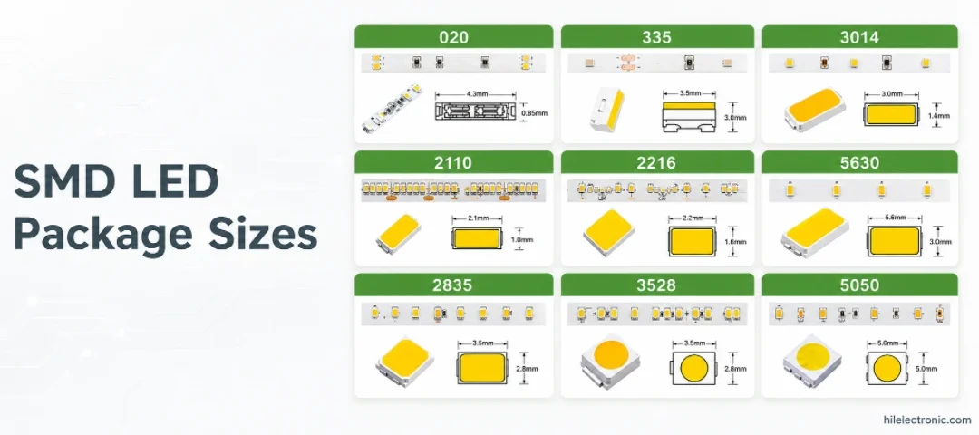
SMD LED Package Sizes: 2835 vs 5050 vs 3528 and PCB Selection
Figure 1. SMD LED package sizes image for PCB...
How to get a quote for PCBs
Let‘s run DFM/DFA analysis for you and get back to you with a report. You can upload your files securely through our website. We require the following information in order to give you a quote:
-
- Gerber, ODB++, or .pcb, spec.
- BOM list if you require assembly
- Quantity
- Turn time
In addition to PCB manufacturing, we offer a comprehensive range of electronic services, including PCB design, PCBA, and turnkey solutions. Whether you need help with prototyping, design verification, component sourcing, or mass production, we provide end-to-end support to ensure your project’s success.
For PCBA services, please provide your BOM (Bill of Materials) and any specific assembly instructions. We also offer DFM/DFA analysis to optimize your designs for manufacturability and assembly, ensuring a smooth production process.