
How to Cut PCB: Professional Techniques & Tools Guide

1. Introduction
Knowing how to cut PCB correctly is essential for achieving custom dimensions, separating panelized boards, or removing unwanted sections. The cutting method directly affects the board’s electrical performance, mechanical reliability, and edge quality. This guide covers proven techniques, proper tool selection, and critical safety considerations for both manual and automated PCB cutting operations.
2. Fundamentals of Cutting PCBs
2.1 PCB Materials and Cutting Challenges
Different PCB substrates present distinct cutting challenges. FR-4, the most common material, contains woven fiberglass reinforcement that resists cutting and generates abrasive dust. Flexible PCBs require gentler handling to prevent tearing, while multilayer boards demand precise control to avoid delamination between layers. Understanding your board’s composition is the first step in selecting an appropriate cutting approach.
2.2 Cutting vs Depanelization
General PCB cutting involves separating boards to custom sizes, while depanelization specifically refers to separating individual units from a manufactured panel. Depanelization often relies on pre-designed features like V-scores or mouse bites that define separation lines during PCB fabrication. Effective panel design anticipates the cutting method, reducing stress on components and ensuring clean separation edges.

Manual Cutting
3. PCB Cutting Techniques and Tools
3.1 Manual Cutting Techniques
Manual methods suit prototyping, small-batch production, and situations where specialized equipment is unavailable. Each tool addresses specific material thicknesses and cut complexity requirements.
3.1.1 Utility Knife / Precision Knife
Precision knives work best for thin, single-layer boards requiring straight cuts. The technique involves scoring both sides repeatedly along a straight edge, then snapping the board along the groove. This method is inexpensive and accessible but unsuitable for thick FR-4 or curved profiles.
3.1.2 Metal Shears / Heavy-Duty Shears
Heavy-duty shears handle FR-4 and similar rigid materials efficiently. They deliver fast, relatively clean cuts for straight edges. However, shears may leave slightly rough edges requiring post-processing, and applying excessive force risks cracking the laminate structure.
3.1.3 Nibblers / Manual Depanel Bars
Nibblers progressively remove small material sections, making them ideal for irregular shapes or thick boards. This nibbling action accommodates curved contours that straight-cutting tools cannot achieve. The tradeoff is slower operation and edges that typically need finishing work.
3.1.4 Table Saw / Guillotine Style Cutter
Table saws and guillotine cutters provide stability for larger boards and faster separation of multiple pieces. Proper fixturing prevents board movement during cutting. These tools require dust collection systems and regular blade maintenance to ensure consistent cut quality.
3.2 Automated PCB Cutting Methods
Industrial environments demand higher precision, repeatability, and throughput than manual methods can deliver. Automated cutting systems address these requirements across various board types and production volumes.
3.2.1 V-Scoring (V-Cut)
V-scoring creates shallow V-shaped grooves along intended separation lines during PCB fabrication. Boards later separate by applying controlled bending force along the score. This method excels for high-volume straight-line depanelization but cannot accommodate curved separations.
3.2.2 CNC Routing
CNC routers follow programmed paths to cut PCBs with exceptional precision. The method handles complex contours, maintains tight tolerances, and produces smooth edges suitable for enclosure fitting. Router bit selection and feed rate optimization are critical for different materials and thicknesses.
3.2.3 Sawing / Depanelizing Saws
Depanelizing saws use circular blades for rapid straight cuts through thick or high-volume boards. Dedicated PCB saws incorporate dust extraction and cooling systems. Blade selection must match the substrate material to minimize chipping and heat generation.
3.2.4 Laser Cutting
Laser cutting provides non-contact, high-precision separation ideal for flexible circuits and fine-pitch applications. The process eliminates mechanical stress on components near cut lines. Equipment costs and material compatibility considerations limit adoption to specialized applications.
3.2.5 Water Jet Cutting
Water jet systems use high-pressure abrasive streams for cutting without thermal effects. This cold-cutting process suits heat-sensitive assemblies and thick boards. Higher equipment and operating costs restrict water jet cutting to applications where thermal neutrality is paramount.

Automated Cutting
4. Step-by-Step Guidance for Cutting PCBs
4.1 Preparation Phase
Clean the PCB surface to remove contaminants that could interfere with marking or cutting. Measure carefully and mark cut lines using appropriate tools—fine-tip markers for manual work or CAD files for CNC operations. Secure the board firmly using clamps or vacuum fixtures to prevent movement during cutting.
4.2 Cutting Operation
Execute the cut according to your selected method. For manual tools, maintain steady pressure and consistent speed along marked lines. For automated systems, verify program parameters including cutting depth, feed rate, and tool speed before initiating the operation. Monitor the process for any deviation from expected behavior.
4.3 Post-Processing
Remove burrs and rough edges using fine-grit sandpaper or dedicated deburring tools. Inspect cut edges for delamination, cracks, or fiber protrusion. Clean all cutting debris from the board surface and work area. Verify dimensional accuracy against specifications before proceeding to assembly.
5. Safety and Best Practices for PCB Cutting
PCB cutting generates fiberglass dust that poses respiratory hazards. Always wear appropriate PPE including safety glasses, dust masks rated for fine particles, and protective gloves. Maintain adequate ventilation or use dust extraction systems in the cutting area.
Perform test cuts on scrap material when using new tools or unfamiliar substrates. Adjust cutting parameters to minimize mechanical stress on boards with populated components. Keep tools sharp and properly maintained—dull blades increase cutting force, heat generation, and edge damage risk.
6. Advanced Topics
6.1 Design-for-Depanelization
Incorporate separation features during PCB design to simplify cutting operations. V-score lines, mouse bites, and routed slots reduce post-fabrication processing. Position these features away from sensitive components and traces to prevent damage during separation.
6.2 Comparing PCB Cutting Method Performance
| Method | Precision | Edge Quality | Speed | Cost |
|---|---|---|---|---|
| V-Scoring | Medium | Good | High | Low |
| CNC Routing | High | Excellent | Medium | Medium |
| Laser Cutting | Very High | Excellent | Medium | High |
| Manual Tools | Low-Medium | Variable | Low | Low |
| Water Jet | High | Excellent | Low | High |
7. Summary
Selecting the right approach to cut PCB depends on material type, board thickness, required edge quality, and production volume. Manual methods serve prototyping and small quantities effectively, while automated techniques deliver the consistency and throughput needed for production environments.
Proper preparation, appropriate tool selection, and rigorous safety practices ensure successful results. Post-processing and inspection complete the workflow, verifying that cut boards meet specifications for downstream assembly operations.

Recommended Posts

RF Transceiver PCB Manufacturing and Assembly
Table of contentsRF Transceiver PCB Manufacturing and...
RFSoC Board PCB Manufacturing and Assembly One-Stop Service
Highleap Electronics supports customer-designed RFSOC...
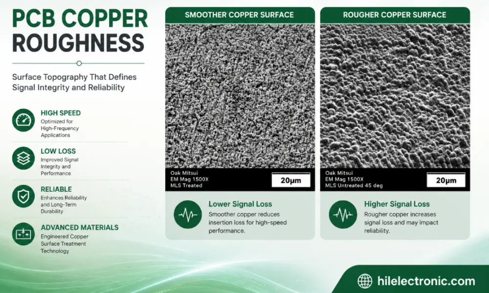
PCB Copper Roughness: Signal Loss, Material Selection and Manufacturing Control
Table of contentsWhat Is PCB Copper Roughness?How Copper...
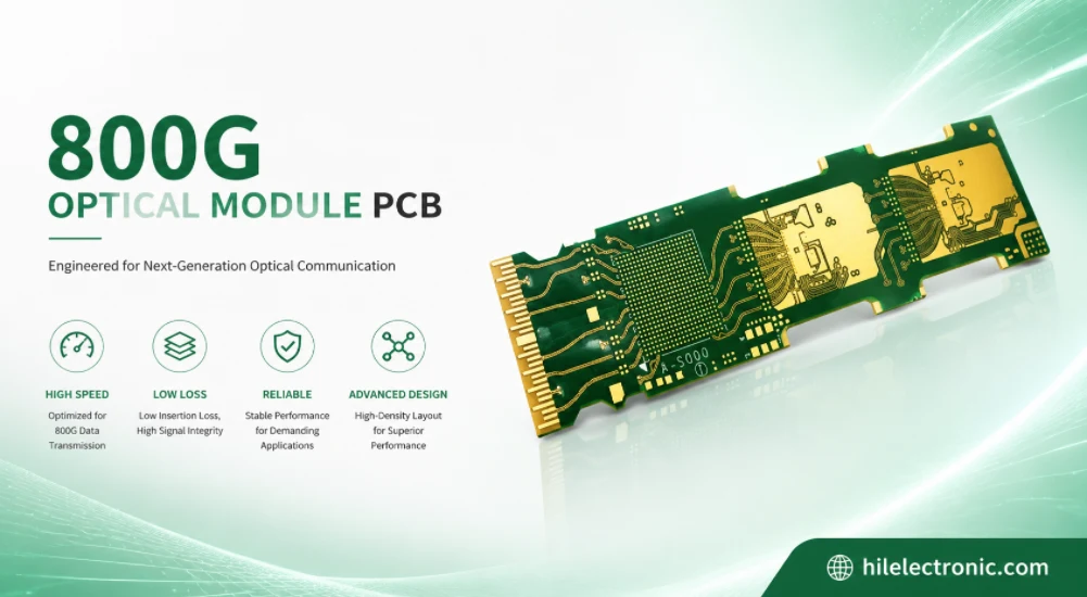
800G Optical Module PCB Manufacturing and Assembly Service
Table of contentsWhat Makes an 800G Optical Module PCB...
How to get a quote for PCBs
Let‘s run DFM/DFA analysis for you and get back to you with a report. You can upload your files securely through our website. We require the following information in order to give you a quote:
-
- Gerber, ODB++, or .pcb, spec.
- BOM list if you require assembly
- Quantity
- Turn time
In addition to PCB manufacturing, we offer a comprehensive range of electronic services, including PCB design, PCBA, and turnkey solutions. Whether you need help with prototyping, design verification, component sourcing, or mass production, we provide end-to-end support to ensure your project’s success.
For PCBA services, please provide your BOM (Bill of Materials) and any specific assembly instructions. We also offer DFM/DFA analysis to optimize your designs for manufacturability and assembly, ensuring a smooth production process.