
Electrical Testing PCB Flying Probe vs ICT vs FCT

Table of Contents
- Bare-Board vs. Assembled PCB Electrical Testing
- Flying Probe vs. ICT Fixture: Cost, Coverage, and When to Use Each
- PCB Test Point Design Rules for Full Coverage
- PCB Test Coverage: How to Calculate Before Layout Is Final
- Impedance Testing, Hipot, and RF Tests for High-Speed PCBs
- AOI, X-Ray, and Functional Test After Assembly
- How the CAM Engineer Builds the Electrical Test Program
- PCB Electrical Test Specification: What to Require from Your Manufacturer
Engineers searching for electrical testing PCB solutions rarely want the same thing. Some are choosing between flying probe and ICT fixture. Some are tracing shorts, opens, or impedance faults. Some need a fabricator who commits to 100% electrical test with per-lot documentation. Some are writing a test specification and need to know exactly what thresholds and methods to specify. And some need to understand the CAM engineer’s role — because the decisions made before the first board runs determine whether the test program catches real defects or produces passing reports that miss critical faults.
Get PCB with 100% Electrical Test
Bare-Board vs. Assembled PCB Electrical Testing
PCB electrical testing happens at two distinct stages, and they catch different defect classes — neither substitutes for the other.
Bare-board electrical test is performed before components are placed. Every net is tested for continuity (≤10Ω) and isolation (≥10MΩ at 250VDC). It catches fabrication defects: etching opens and shorts, drill misregistration, via barrel opens, and inner-layer delamination shorts. Board surface is fully accessible, so net coverage reaches 95–99%.
Post-assembly electrical test is performed after soldering. Coverage drops because component bodies block probe access to pads underneath. On BGA-heavy boards, accessible coverage typically falls to 60–80%.
| Defect Type | Bare-Board E-Test | Assembled ICT | Functional Test | What Catches It |
|---|---|---|---|---|
| Etching open or short | ✓ | Partial | Partial | Bare-board test |
| Via plating below spec | ✗ | ✗ | ✗ | Cross-section inspection only |
| Trace impedance out of spec | ✗ | ✗ | Partial | TDR coupon measurement |
| Wrong component value | ✗ | ✓ | Partial | ICT component measurement |
| BGA solder joint void | ✗ | Partial | Partial | X-ray inspection |
| Solder open under BGA | ✗ | Partial | ✓ | Functional test or boundary scan |
What “100% Electrical Testing” Actually Guarantees
When a fabricator commits to 100% electrical testing, it means every bare board is tested before shipping — no sampling. It covers continuity and isolation on all nets. It does not automatically guarantee impedance verification or cross-section inspection — those require explicit specification.
At Highleap, 100% bare-board electrical testing per IPC-9252 is standard on every order. Per-lot test reports ship with the boards. Request the report format before placing the order if your procurement specification requires written test evidence.
Flying Probe vs. ICT Fixture: Cost, Coverage, and When to Use Each
| Factor | Flying Probe | ICT Bed-of-Nails Fixture |
|---|---|---|
| Fixture / setup cost | $0–$300 (programming only) | $100+ simple; $1,000–$3,000+ complex |
| Cost per board | $5–$25 | $0.50–$4.00 after amortization |
| Test time per board | 5–20 minutes | 15–90 seconds |
| Break-even volume | Always justified at low volume | 300–1,000 boards typically |
| Minimum test pad size | 0.30mm | 0.80–1.00mm |
| Grid requirement | None | 1.27mm min, 2.54mm preferred |
| HDI microvia access | Good — reaches 0.25mm land pads | Limited — pogo pins too large |
| Net coverage (bare board) | 95–99% | 99%+ |
| Net coverage (assembled) | 70–90% | 60–80% on BGA-heavy boards |
| Design change flexibility | High — reprogram only | Low — fixture must be rebuilt |
When to Use Each
- <100 boards / prototypes: Flying probe always. Fixture investment not justified; revisions are expected.
- 100–500 boards: Flying probe for bare board. ICT only if layout supports it and design is stable.
- 500–5,000 boards/year: Evaluate against throughput need. A $1,000 fixture at 500 units = $2/board — usually worth it when cycle time matters.
- >5,000 boards/year: ICT fixture for throughput; flying probe for geometrically inaccessible nets only.
- HDI with microvias: Flying probe handles microvia pads better. Hybrid works: ICT for main nets, flying probe for microvia-only nets.
- High-mix / frequent revisions: Flying probe avoids fixture obsolescence — no rebuild needed when the board revises.
Why BGA Coverage Falls Below 70%
BGA, QFN, and LGA packages sit on top of their solder joints — probes cannot reach them from outside. On a board with three large BGAs, 30–40% of nets may have no accessible probe point on either board side. Solutions: add test vias for critical BGA nets during layout; use boundary scan (JTAG) on compliant ICs; or cover inaccessible subsystems with functional test.
PCB Test Point Design Rules for Full Coverage
Test coverage is determined during PCB layout — not by the test engineer after boards are built. These rules must be applied before routing is complete.
ICT Fixture Requirements
- Test pad diameter: 1.0mm preferred, 0.80mm absolute minimum
- Clearance to component body: 2.5mm minimum
- Test pad spacing: 2.54mm preferred; 1.27mm minimum. Below 1.27mm requires custom fixture at much higher cost
- Single-side placement: Reduces fixture cost 40–60% by eliminating the second fixture plate
- Coverage target: One test point per net minimum; one per net node for fault isolation capability
Flying Probe Requirements
- Minimum pad: 0.30mm — no grid constraint, both sides accessible, microvia land pads reachable
- Neither probe type can reach nets with no surface-accessible pad. Nets entirely under BGA packages require supplementary methods regardless of probe choice
Omitting test points to save board area always results in the same outcomes: slow flying probe with incomplete coverage, an ICT fixture at 50–60% coverage providing false confidence, or no automated PCB electrical testing at all. Test point copper costs nothing at fabrication.
PCB Test Coverage: How to Calculate Before Layout Is Final
Net Coverage vs. Node Coverage
“100% electrical test” means 100% of nets have at least one accessible test point — not that every node is independently probed. A five-node net tested only from its endpoints leaves three intermediate nodes verified by inference. A marginal cold joint at a middle node with 7Ω resistance on a 10Ω threshold passes undetected.
Three metrics that matter:
- Net coverage: % of all nets with at least one accessible point. Target 100% on bare board.
- Node coverage: % of all net nodes (pads, junctions, vias) directly probed. >80% is solid; <60% needs documentation and mitigation.
- Fault coverage: % of all possible fault types the test program can detect — the most meaningful number and the hardest to quantify without test simulation tools.
Coverage Calculation Before Finalizing Layout
- Export full net list with node count from your PCB CAD tool
- Flag each net: does it have at least one accessible pad (≥1.0mm for fixture, ≥0.30mm for flying probe)?
- Covered nets ÷ total nets × 100 = estimated net coverage
- If below 85%: add test vias or pads now, before layout is finalized
Defect Escape Rate by Test Strategy
| Test Strategy | Defect Escape Rate | Primary Gaps |
|---|---|---|
| No test | 500–3,000 ppm | Everything |
| Bare-board test only | 200–800 ppm | Assembly defects, impedance errors, marginal via plating |
| Bare-board + assembled ICT | 50–200 ppm | Under-BGA opens, impedance, latent plating |
| Bare-board + ICT + functional test | 10–50 ppm | Latent and intermittent failures |
| Full stack + X-ray + burn-in | <10 ppm | Required for Class 3 medical, aerospace, automotive |

Impedance Testing, Hipot, and RF Tests for High-Speed PCBs
TDR Impedance Verification
Standard continuity test confirms a trace exists — it does not verify its impedance. A trace that etched 3µm narrower than designed measures correct resistance at DC but may be 53Ω instead of 50Ω — a signal integrity problem invisible to standard PCB electrical testing.
TDR (time-domain reflectometry) injects a fast voltage edge and measures the reflected waveform. Standard acceptance: ±10% of nominal; tight designs specify ±5%. To make this a production deliverable, specify a TDR coupon in the panel: a trace with identical geometry running along the panel edge, with the layer, reference planes, trace width, target impedance, and tolerance written in the fabrication notes. One coupon per panel per impedance specification. Without this, you have no lot-specific impedance evidence.
For controlled-impedance PCBs — DDR5, PCIe, USB 3.x, RF — TDR is not optional.
Hipot Testing
Hipot applies elevated voltage between isolated nets to verify no breakdown path exists at operating voltage. A pair showing 10MΩ at 250VDC may still break down at 500V if a mask pinhole or contamination path is present. Required for medical devices (IEC 60601: 1,500–4,000V), automotive power electronics above 48V (500–1,000V), industrial mains isolation (IEC 61010: 1,000–1,500V), and power supply regulatory compliance (IEC 62368: 1,500–3,000V). Cost: $0.20–$0.80/board. Applied 100% in Class 3 and medical programs.
RF Network Analysis Above 1 GHz
For RF PCB testing above 1 GHz, vector network analysis (VNA) measures S-parameters — insertion loss, return loss, and port isolation — across frequency. Used for first-article verification and statistical sampling. Required for RF modules, antenna circuits, and filter networks above 1 GHz.
AOI, X-Ray, and Functional Test After Assembly
AOI
Automated optical inspection runs after every SMT reflow pass at 30–120 seconds per board, 100% of panels. It catches missing components, reversed polarity, tombstoned passives, visible solder bridges, and BGA placement misalignment. It cannot see under package bodies, cold joints that look correct, wrong-value parts, or solder voids inside joints.
X-Ray
X-ray images solder joints under BGA, QFN, and LGA packages — detecting bridges inside the ball array, opens, and voids above 25% of ball area. Run 100% on high-reliability products and all BGA rework; first-article plus statistical sampling for standard production.
Functional Circuit Test
Functional circuit testing powers the board and exercises its actual operation. It catches what no electrical test can: boards with correct components and clean assembly that still fail their specification — wrong firmware, marginal timing, design-related escapes. Custom fixture cost: $5,000–$50,000+. Justified above roughly 1,000 units/year when field return cost exceeds fixture development.
How the CAM Engineer Builds the Electrical Test Program
Most engineers treat PCB electrical testing as something that happens to the finished board. In practice, the decisions that determine test quality are made earlier — by the CAM engineer, before production starts.
Four Things the CAM Engineer Does Before the First Board Runs
Netlist extraction and verification. The CAM engineer extracts the copper netlist from your Gerber or ODB++ files and compares it against your IPC-356 design netlist. Discrepancies — pads on the wrong layer, missing connections, extra connections — are caught before the board is built. Without an IPC-356 file, the test program is built from Gerber geometry alone, meaning any Gerber-to-design discrepancy goes undetected until a board fails.
Test point accessibility mapping. Every net is mapped against available probe access points. Nets with no accessible point are formally flagged as non-testable. A CAM engineer who silently skips inaccessible nets produces a report showing 100% of tested nets passing — while a significant fraction was never tested. This distinction is the difference between a coverage report and a coverage claim.
Threshold assignment by net class. Power rails, signal nets, high-voltage isolation nets, and RF nets each carry different continuity and isolation requirements. The CAM engineer assigns thresholds net-by-net per your specification. If you specify only “IPC-9252,” they apply standard defaults, which may not match your design’s actual needs.
Flying probe path optimization. The CAM engineer programs the probe sequence — grouping nearby test points to minimize arm travel. Poor path optimization adds 20–40% to test time per board on complex designs.
What Weak CAM Test Engineering Looks Like
- Test reports showing 100% pass with no non-testable net count disclosed
- Test programs built from Gerber only, with no design netlist comparison
- A single 10Ω continuity threshold applied to all nets regardless of function
- No impedance verification on high-speed PCB designs because no one asked
When evaluating an electrical testing PCB supplier, ask: “How do you handle nets with no accessible test point, and how is that reflected in the test report?” The answer reveals whether their CAM process produces real coverage data or coverage that only looks complete.
Always Include the IPC-356 Netlist File
IPC-356 is a standard netlist format exportable from most PCB EDA tools. It lists every net by name with every pad and via land that belongs to it. Providing it enables the CAM engineer to verify the Gerber netlist against design intent, assign net-specific thresholds by name rather than by geometry inference, and generate a named-net coverage report that designers can actually read. Without it, every net is anonymous copper and the test program is built from geometry alone. It takes 30 seconds to export and prevents the ambiguity that causes test escapes.
PCB Electrical Test Specification: What to Require from Your Manufacturer
“100% electrical test to IPC-9252” is a methodology reference — not a specification. The standard provides the framework; you must define the acceptance values. A complete specification includes:
- Continuity threshold: ≤10Ω default. Power or high-current nets: ≤5Ω or tighter. Specify by net class, not one value for the whole board.
- Isolation threshold: ≥10MΩ at 250VDC default. High-impedance analog: ≥500MΩ on specific net pairs.
- Test voltage: 250VDC standard. Specify 500V+ for elevated operating voltage or regulatory isolation requirements.
- Impedance verification: TDR coupon geometry, target, tolerance, and per-lot reporting. If omitted, no lot-specific impedance evidence exists.
- Test method and coverage: Flying probe or fixture; excluded nets and justification; minimum acceptable coverage percentage.
- Post-assembly inspection: AOI scope (100% or sampled); X-ray scope; ICT program revision; first-article inspection requirements.
- Failure disposition: Scrap, rework, or conditional accept — with documentation requirements for each outcome.
- Records retention: Per-panel test report format, retention period, and access method for field failure analysis.
Three Specification Errors That Create Hidden Quality Risk
- No acceptance values: “IPC-9252” alone means the fabricator applies their in-house defaults, which may not match your design.
- No TDR on controlled-impedance boards: Without a coupon specification, you have no production evidence that impedance is within spec — only the fabricator’s process statistics.
- Claiming 100% assembled coverage without analysis: BGA coverage gaps that aren’t acknowledged create defect escape paths that look acceptable on paper and fail in the field.
Highleap’s PCB Electrical Test Capabilities
Highleap Electronics includes 100% electrical testing as standard on every bare-board order:
- Flying probe: 4 systems, ±15µm accuracy — 100% net coverage on every panel, prototype through production
- Universal grid testers: For high-volume orders above 500 boards per batch
- TDR impedance: ±5% tolerance; lot-specific waveform report included with all impedance-controlled PCB orders at no extra charge
- Hipot: Up to 3,000VDC for medical and high-voltage isolation applications
- Post-assembly AOI: 100% after every reflow pass
- X-ray: 2D and 2.5D BGA and QFN joint verification — 100% or sampled per specification
- Functional test: Custom fixture and program development with per-unit serial number traceability
- Test documentation: Per-lot electrical test reports, TDR archives, first-article packages — standard deliverables, not add-ons

Recommended Posts

RF Transceiver PCB Manufacturing and Assembly
Table of contentsRF Transceiver PCB Manufacturing and...
RFSoC Board PCB Manufacturing and Assembly One-Stop Service
Highleap Electronics supports customer-designed RFSOC...
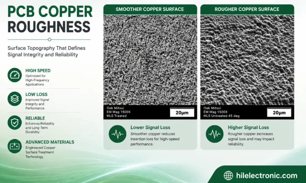
PCB Copper Roughness: Signal Loss, Material Selection and Manufacturing Control
Table of contentsWhat Is PCB Copper Roughness?How Copper...
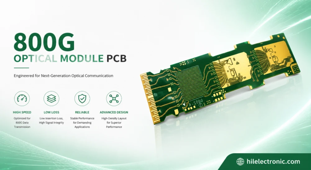
800G Optical Module PCB Manufacturing and Assembly Service
Table of contentsWhat Makes an 800G Optical Module PCB...
How to get a quote for PCBs
Let‘s run DFM/DFA analysis for you and get back to you with a report. You can upload your files securely through our website. We require the following information in order to give you a quote:
-
- Gerber, ODB++, or .pcb, spec.
- BOM list if you require assembly
- Quantity
- Turn time
For PCBA services, please provide your BOM (Bill of Materials) and any specific assembly instructions. We also offer DFM/DFA analysis to optimize your designs for manufacturability and assembly, ensuring a smooth production process.