
PCB Assembly Files Complete Guide

If you are getting ready to place a PCB assembly order, one of the most common reasons for delays is not the board design itself but the file package sent to the manufacturer. Many projects run into problems because the customer submits incomplete PCB assembly files, mismatched revisions, unclear BOM data, or placement files that do not match the actual layout.
In real production, missing or incorrect files can lead to repeated engineering questions, sourcing delays, wrong component placement, unexpected cost increases, and longer lead times. Working with an experienced PCB assembly services provider helps, but the project still moves faster when the file package is complete from the start.
This guide explains what PCB assembly files you need, what each file is used for, what usually goes wrong, and how to prepare your data correctly so your project can move from quotation to production with fewer problems.
What PCB Assembly Files Are and Why They Matter
PCB assembly files are the manufacturing documents used by the supplier to build, inspect, and test your board correctly. These files do much more than show what the PCB looks like. They tell the manufacturer what parts to buy, where every component goes, how each part should be oriented, and what testing or programming steps are required before shipment.
When these files are incomplete, even a simple project can slow down. The purchasing team may not know which parts to order. The SMT team may not trust the rotation data. The engineering team may have to stop the job to confirm polarity or clarify missing notes. This is why complete PCB assembly files directly affect cost, lead time, and production accuracy.
The Problems Customers Usually Face Before Production Starts
Most customers do not struggle because they lack technical knowledge. The real problem is that PCB assembly depends on several separate data sets, and if just one file is inconsistent, the whole job can pause. These are the issues manufacturers see most often.
BOM and layout do not match
The BOM may show one manufacturer part number while the placement data and silkscreen reference another design revision. This forces the engineering team to ask follow-up questions before purchasing or assembly can begin.
Pick and place data is technically complete but still wrong
Coordinates may be correct, but rotation values can still be wrong. This is especially common when files are exported from different CAD systems or when footprints use nonstandard rotation conventions.
Special assembly notes are missing
Customers often forget to mention hand-soldered connectors, selective soldering, conformal coating, heat sinks, labels, firmware loading, or packaging requirements. Without these notes, the manufacturer may quote incorrectly or discover the issue too late.
Multiple file revisions are mixed together
It is common to see a new BOM sent together with old Gerber data or an updated pick and place file that does not match the latest layout. When revisions are mixed, the risk of assembly errors increases sharply.
Testing requirements are not defined early
Many customers assume the board will simply be assembled and shipped, but many projects also need programming, inspection criteria, or functional verification. If this is not discussed early, the final production stage becomes slower and more expensive.

What Files You Should Prepare for a PCB Assembly Order
For most projects, a complete PCB assembly package should include a BOM, Gerber or ODB++ data, pick and place data, assembly drawings, drill files, and any testing or programming requirements. Some simple boards may not need every document, but most commercial orders move faster and more accurately when the full package is prepared.
Bill of Materials BOM
The BOM is the purchasing and assembly reference for your project. It tells the manufacturer exactly which components must be installed on the board. A good BOM should include reference designators, manufacturer part numbers, part descriptions, package types, quantities, approved manufacturers, and clear DNI or DNP markings.
The BOM is especially important for turnkey PCB assembly because the supplier uses it to purchase parts, check stock availability, review alternatives, and confirm whether all materials can be sourced within the required schedule. A clear BOM also improves components sourcing and reduces delays caused by unclear substitutions.
Gerber or ODB Plus Plus data
Gerber files define the physical PCB layers and are essential for PCB fabrication. They show copper layers, solder mask, silkscreen, paste layers, board outline, and other fabrication details. Some customers prefer ODB++ because it combines fabrication and assembly information in one package and reduces the chance of missing files.
Pick and place or centroid data
This file tells the automated assembly line where each component should be placed and at what angle. It usually includes reference designators, X and Y coordinates, rotation, board side, and footprint information. Accurate placement data is critical when the supplier relies on strong SMT capability to run fine-pitch or dense assembly jobs.
Assembly drawings and drill files
Assembly drawings help the production and inspection teams confirm polarity, connector direction, pin 1 location, and special mounting details. Drill files are required whenever the board includes through-hole features, connectors, mounting holes, or mixed-technology assembly.
Schematics and testing instructions
Schematics are not always mandatory, but they can be very helpful for complex designs, alternate part review, troubleshooting, and engineering clarification. If the product also needs programming, inspection criteria, or final verification, those requirements should be included from the beginning.
What Goes Wrong in Each File and How to Avoid It
Knowing which files are needed is only part of the job. The bigger issue is knowing where customers usually make mistakes.
BOM problems
- using distributor numbers instead of manufacturer part numbers
- forgetting to mark non-installed parts
- listing multiple approved parts without clear priority
- sending a BOM that does not match the final layout revision
Gerber and ODB++ problems
- sending files from an older revision
- forgetting drill data or board outline details
- not including mechanical details for special features
- failing to mention special materials or process notes
Pick and place problems
- rotation values do not match actual footprint orientation
- bottom side parts are exported incorrectly
- reference designators do not match the BOM
- coordinates are based on the wrong board origin
Before submission, manually check a few sensitive components such as ICs, connectors, diodes, LEDs, and electrolytic capacitors. A quick manual review often catches the biggest problems before production starts.
Testing Programming and Special Notes That Customers Often Miss
Many delays happen because customers focus only on soldering and forget that production may also include programming, inspection, and functional verification. If the board needs more than assembly, that information should be included in the file package from the start.
Planning for PCB DFT early helps define test points, inspection access, and verification methods before the board reaches the final stage. For finished boards that require validation before shipment, clear requirements for functional testing should be documented early. If the project includes firmware loading or device setup, the manufacturer may also need files and instructions for IC programming.
Testing related information may include:
- test procedures
- programming files
- firmware versions
- test point locations
- acceptance criteria
- pass and fail definitions
In addition to testing, many projects also need a short notes document that covers special requirements such as hand soldering, heat sink installation, conformal coating, adhesive use, label placement, panelization, packaging instructions, or special handling for sensitive parts.

How Manufacturers Use Your Files During Engineering Review
Customers often think these files are only for production, but they are first used during engineering review. This is the stage where the supplier checks manufacturability, sourcing feasibility, assembly risk, and test readiness.
During review, the manufacturer may evaluate the project from a PCB DFA perspective to identify assembly risks before production starts. File consistency matters here because a good review can prevent expensive mistakes later.
The review process usually includes:
- checking the BOM for sourcing feasibility
- checking Gerber data against board requirements
- reviewing placement files for coordinates and rotation logic
- checking assembly drawings for polarity and visual confirmation
- reviewing testing requirements for practicality and completeness
The better your file package is, the faster this stage moves and the more accurate the final quote and lead time will be.
How to Prepare PCB Assembly Files So the Project Moves Faster
Use one final revision only
Make sure the BOM, Gerber, placement files, drawings, and notes all come from the same project revision. Mixed revisions are one of the biggest causes of delay.
Use clear file names
Simple names such as BOM RevB, Gerber RevB, Pick and Place RevB, and Assembly Drawing RevB make review easier and reduce confusion.
Flag critical parts early
If a component is hard to source, cannot be substituted, or must be installed with a specific orientation or process, mention it clearly before purchasing starts.
Do not rely on one file alone
No single file explains everything. The BOM, Gerber, placement file, drawings, and notes should support each other rather than contradict each other.
Think beyond assembly only
If the board must also be programmed, tested, labeled, or packed in a special way, include those requirements early instead of discussing them after production starts.
PCB Assembly Files Checklist Before You Send the Order
Before submitting your project, check that the file package includes:
- BOM with correct manufacturer part numbers
- Gerber files or ODB++ files
- drill files if required
- pick and place or centroid data
- top and bottom assembly drawings
- special process notes
- schematics if available
- testing and programming requirements if needed
- one consistent revision across all files
This checklist may look simple, but it solves many of the issues that usually delay quotation and production. It also helps customers get faster responses, fewer engineering questions, and more predictable delivery schedules, especially for low volume PCB assembly and new product introduction work.
Conclusion
PCB assembly files are the foundation of a successful PCBA project. If the file package is complete, clear, and consistent, the manufacturer can review the design faster, purchase parts more accurately, program the line correctly, and complete inspection and testing with fewer interruptions.
At a minimum, most projects should include a BOM, Gerber or ODB++ data, drill files, pick and place data, assembly drawings, and any required notes for testing, programming, or special handling. Customers who prepare these files carefully usually get faster quotations, fewer questions, better production accuracy, and smoother delivery.
If you want to reduce production risk and speed up your next order, the best place to start is with a complete and accurate PCB assembly file package and a reliable partner for PCB assembly services.

Recommended Posts
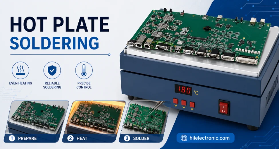
Hot Plate Soldering: Process, Limits, and Reflow Comparison
Figure 1. hot plate soldering image for Highleap...
IPC J-STD-001: Classes, Requirements, and RFQ Specification
Figure 1. IPC J-STD-001 image for Highleap Electronics PCB...
Solder Paste for SMT Assembly: Types, Storage, and Printing Defects
Figure 1. Solder paste selection affects SMT print...
Through-Hole Soldering: Best Practices and Defect Control
Figure 1. Through-hole soldering is used for connectors,...