
Beginner’s guide to Metal Core PCBs

Metal Core Printed Circuit Boards (MCPCBs) are essential in today’s electronics for efficiently managing heat generated by high-power components. By integrating a metal substrate—usually aluminum, copper, or a copper alloy—these boards offer superior thermal conductivity compared to standard FR4 PCBs.
For beginners, understanding how MCPCBs work starts with knowing their core materials, construction types, and performance benefits. This article provides a clear overview of the commonly used cores, main structural types, key advantages, and practical applications of Metal Core PCBs across industries such as LED lighting, automotive electronics, and power systems.
What is Metal Core PCB?
Metal Core PCBs (MCPCBs) represent a specialized category of printed circuit boards that integrate metal substrates—primarily aluminum or copper—as their base material instead of traditional FR4 fiberglass. This fundamental design difference enables thermal conductivity rates of 1-4 W/mK, dramatically outperforming standard PCBs at 0.3 W/mK.
The architecture consists of three essential layers working in harmony:
- Metal Base Layer – Provides structural support and primary heat dissipation pathway
- Thermally Conductive Dielectric – Electrically isolates while maintaining thermal transfer
- Copper Circuit Layer – Carries electrical signals with standard thicknesses from 1-4 oz
This construction creates an efficient thermal management system where heat flows directly from components through the dielectric into the metal substrate, then dissipates across the entire board surface. For applications exceeding 1W per component, this technology becomes critical for maintaining safe operating temperatures and ensuring long-term reliability.

Commonly Used Cores in Metal Core PCBs
Aluminum Core Substrates
Aluminum dominates the metal core PCB market, accounting for over 75% of applications due to its optimal balance of performance and economics. Standard aluminum substrates offer:
- Thermal Performance – 2.0-2.2 W/mK conductivity for efficient heat spreading
- Weight Advantage – 60% lighter than copper alternatives
- Cost Efficiency – 3-5 times less expensive than copper core options
- Machinability – Compatible with standard PCB processing equipment
Common aluminum alloys include 5052 for general applications and 6061 for enhanced mechanical strength. Surface treatments like anodization add corrosion resistance while maintaining thermal performance within 5% of bare metal values.
Copper Core Solutions
Copper substrates excel in extreme thermal and high-frequency applications where performance justifies the premium cost. Key characteristics include:
- Superior Thermal Conductivity – 400 W/mK enables ultra-high power density designs
- Electromagnetic Shielding – Natural EMI protection for sensitive circuits
- Mechanical Strength – 2x stronger than aluminum for vibration-resistant applications
- Temperature Stability – Minimal expansion ensures reliability through thermal cycling
Despite higher costs and processing complexity, copper proves economical when power density exceeds 10W/cm² or when combining thermal management with RF shielding requirements.
Advanced Composite Materials
Emerging materials address specific application challenges beyond traditional metal substrates:
- Aluminum Silicon Carbide (AlSiC) – Tailored CTE matching semiconductor dies (7-9 ppm/°C)
- Copper-Invar-Copper (CIC) – Low expansion for high-reliability military applications
- Copper-Molybdenum – Optimized for laser diode and RF power amplifier modules

Metal Core PCB Types
Main Types of Metal Core PCBs
Single Layer Metal Core PCBs
The simplest and most widely used structure features one copper circuit layer bonded directly to the metal substrate. With minimal dielectric thickness, this configuration delivers excellent thermal conductivity and cost-effective manufacturing, making it ideal for high-volume LED lighting and basic power applications handling up to 50 W of total power dissipation. Fabrication follows standard PCB processes modified for metal bases, including optimized drilling and etching techniques to protect the aluminum core.
Double Layer and Double-Sided Metal Core PCBs
Type 1: Copper – Dielectric – Copper – Dielectric – Core
This type adds a second copper layer separated by a thermally conductive prepreg over the same metal base. The design increases routing density through buried vias while maintaining efficient heat dissipation. It supports more complex circuitry for automotive control modules and power converters operating up to around 100 W. The entire circuit stack is located on one side of the metal substrate, making it suitable for applications that require compact routing without dual-side component placement.
Type 2: Copper – Dielectric – Core – Dielectric – Copper
In this configuration, copper circuits are patterned on both sides of the metal core, allowing components to mount on each surface. Through-hole vias must be insulated from the conductive core to ensure electrical isolation. Although thermal performance is slightly reduced compared to single-layer or double-layer designs, double-sided MCPCBs offer efficient space utilization and are widely used in compact power supplies and other high-density assemblies.
Multi-Layer Metal Core PCBs
For high-density and high-power applications, multiple circuit layers can be stacked above the metal substrate. Blind and buried vias enable complex interconnections, but thermal efficiency decreases beyond four to six layers, and manufacturing costs rise sharply. Such structures are typically used in telecom equipment, high-power LED drivers, and other advanced systems where electrical performance outweighs cost considerations.
Advantages of Metal Core PCBs
Superior Thermal Management
Metal core technology fundamentally transforms heat dissipation in electronic systems:
- 10x Better Heat Spreading – Aluminum cores distribute heat across the entire board area, eliminating localized hotspots
- 50% Junction Temperature Reduction – Direct thermal coupling lowers component temperatures compared to FR4 designs
- Eliminates External Heatsinks – Integrated thermal management reduces system complexity and assembly costs
Enhanced Reliability and Durability
The rigid metal substrate provides mechanical advantages beyond thermal benefits:
- Vibration Resistance – Metal cores reduce PCB flexing, extending solder joint life in harsh environments
- Dimensional Stability – Lower CTE than FR4 reduces stress during thermal cycling
- Extended Product Lifespan – Cooler operation temperatures double MTBF for many components
Weight and Space Optimization
Despite the metal content, these boards often reduce overall system weight:
- 40% Weight Reduction – Eliminating separate heatsinks and thermal interface materials
- 30% Space Savings – Integrated thermal solution enables compact product designs
- Simplified Assembly – Fewer components reduce manufacturing complexity
Environmental Benefits
Metal core PCBs align with sustainability initiatives:
- Recyclable Materials – Aluminum and copper cores are fully recoverable
- Energy Efficiency – Better thermal management reduces cooling requirements
- RoHS Compliant – Lead-free processes compatible with environmental regulations

Metal Core PCB
Applications of Metal Core PCBs
LED Lighting Systems
The LED industry drives the largest demand for metal core PCB manufacturing, with applications spanning:
- High-Power LED Arrays – COB LEDs over 50W require metal substrates to maintain 85°C junction temperatures
- Street and Stadium Lighting – 200-500W fixtures depend on aluminum PCBs for passive cooling
- Automotive Headlights – Metal cores enable adaptive LED matrix systems with 100+ individual emitters
- UV Curing Systems – Industrial UV LEDs generating 20W/cm² rely on copper substrates
Proper thermal management extends LED lifespan from 25,000 to 50,000+ hours while maintaining color consistency and light output.
Power Electronics and Converters
Modern power systems leverage metal core technology for improved efficiency:
- DC-DC Converters – 1kW modules achieve 95%+ efficiency through superior thermal management
- Motor Drives – Variable frequency drives utilize aluminum substrates for IGBT cooling
- Solar Inverters – Metal cores enable higher power density in rooftop installations
- EV Charging Stations – Fast chargers employ copper core boards for 350kW power delivery
Automotive Electronics
Automotive applications demand exceptional reliability under extreme conditions:
- Engine Control Units – Survive 125°C under-hood environments for 15+ years
- LED Headlight Drivers – Adaptive beam systems require precise thermal control
- Electric Vehicle Inverters – Metal substrates handle 100kW+ power conversion
- ADAS Sensors – Radar and lidar systems benefit from integrated EMI shielding
Telecommunications Infrastructure
5G and beyond require advanced thermal solutions:
- Base Station Amplifiers – Massive MIMO systems with 64+ RF chains at 50W each
- Small Cell Units – Compact urban installations demand integrated cooling
- Fiber Optic Transceivers – 400G modules generate significant heat in confined spaces
- Satellite Communications – Space applications utilize specialized metal core materials
Conclusion
Metal Core PCBs play an essential role in managing heat for high-power and high-reliability electronic systems. Understanding their core materials, structure types, and performance advantages provides a solid foundation for anyone starting in PCB design or thermal management. As technology evolves, MCPCBs continue to enable innovations in LED lighting, automotive electronics, and energy-efficient power systems.
For beginners, the key takeaway is that successful thermal performance depends on choosing the right materials and understanding how metal substrates enhance heat dissipation. As your design experience grows, exploring detailed aspects such as dielectric selection, stack-up configuration, and manufacturing constraints will further improve your ability to create reliable high-power circuits.
At Highleap Electronics, we believe that sharing technical knowledge helps engineers make better design decisions. Our team continues to provide educational resources and practical insights into PCB technologies, including Metal Core, HDI, and Flexible PCBs — helping you move from basic understanding to confident application.

Recommended Posts
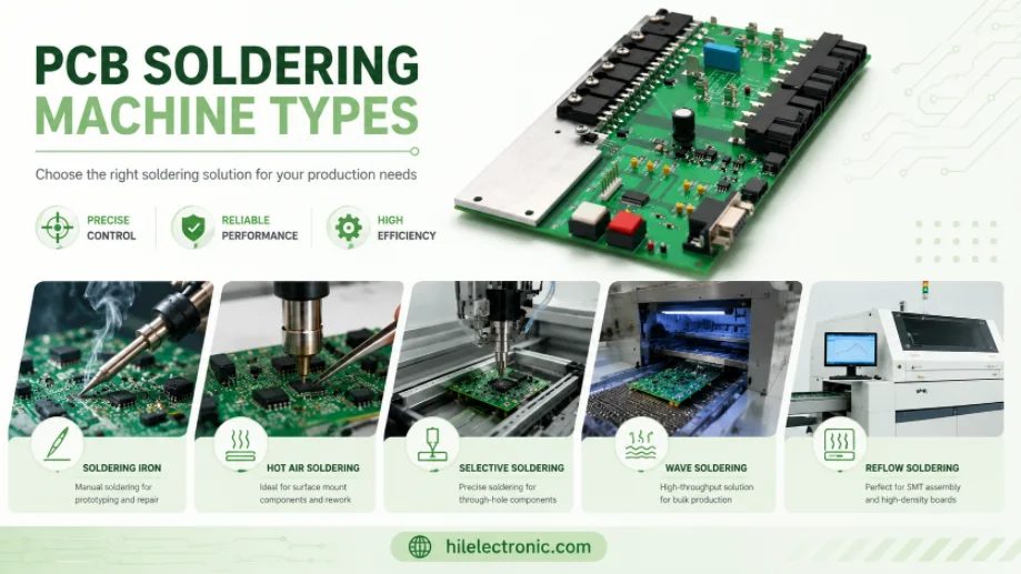
PCB Soldering Machine Types: Reflow, Wave, and Selective Equipment
Figure 1. PCB soldering machine types image for Highleap...
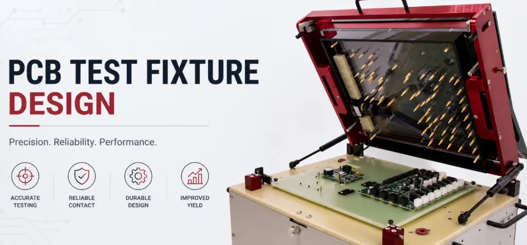
PCB Test Fixture Design: Bed-of-Nails, Flying Probe, and DFT
Figure 1. PCB test fixture design image for Highleap...
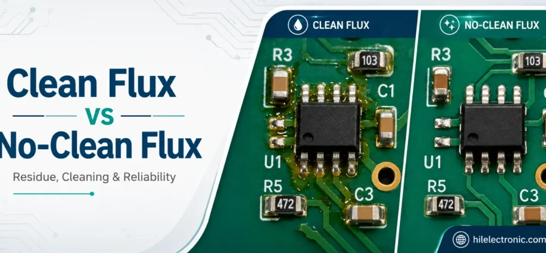
Clean Flux vs No-Clean Flux: Residue, Cleaning, and PCB Reliability
Figure 1. clean flux vs no-clean flux image for Highleap...
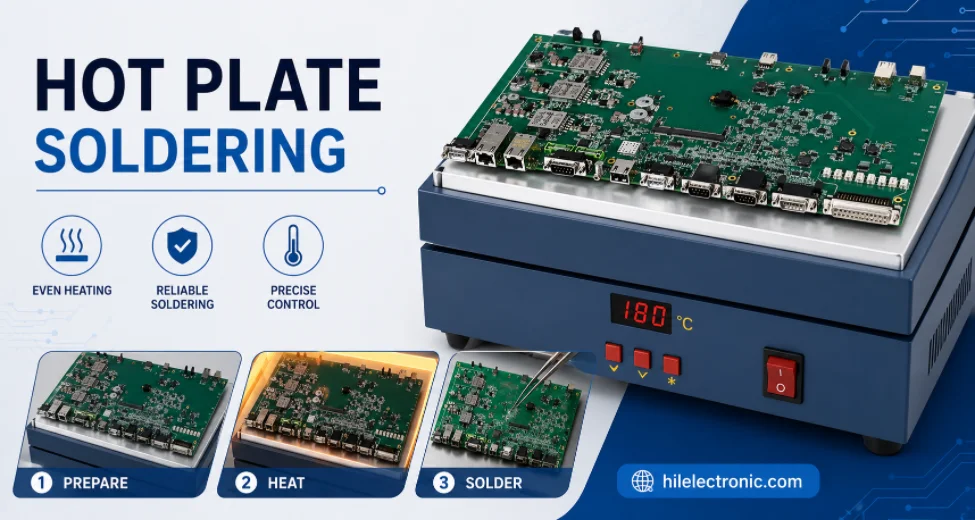
Hot Plate Soldering: Process, Limits, and Reflow Comparison
Figure 1. hot plate soldering image for Highleap...
How to get a quote for PCBs
Let‘s run DFM/DFA analysis for you and get back to you with a report. You can upload your files securely through our website. We require the following information in order to give you a quote:
-
- Gerber, ODB++, or .pcb, spec.
- BOM list if you require assembly
- Quantity
- Turn time
In addition to PCB manufacturing, we offer a comprehensive range of electronic services, including PCB design, PCBA, and turnkey solutions. Whether you need help with prototyping, design verification, component sourcing, or mass production, we provide end-to-end support to ensure your project’s success.
For PCBA services, please provide your BOM (Bill of Materials) and any specific assembly instructions. We also offer DFM/DFA analysis to optimize your designs for manufacturability and assembly, ensuring a smooth production process.