
PCB Mount Transformer: Structure, Types, Applications, and Design Considerations

Figure 1. PCB Mount Transformer
Introduction to PCB Mount Transformers
A PCB mount transformer is a compact electromagnetic component designed for direct installation onto printed circuit boards. Unlike chassis-mount transformers that require separate mechanical fastening, PCB mount transformers integrate seamlessly into board-level designs through standardized pin configurations. This direct-mount approach eliminates external wiring, reduces assembly complexity, and supports automated manufacturing processes.
These transformers serve essential functions in modern electronics: voltage conversion, galvanic isolation, and signal conditioning. As devices shrink and power density increases, the PCB mount transformer has become indispensable in applications ranging from switch-mode power supplies to communication interfaces.
How PCB Mount Transformers Work
Magnetic Induction Fundamentals
A PCB mount transformer operates on Faraday’s principle of electromagnetic induction. The primary winding receives input voltage, generating a magnetic flux within the core. This flux links to the secondary winding, inducing a proportional voltage. The core material—whether ferrite or laminated silicon steel—provides the low-reluctance magnetic path that couples the windings efficiently.
Voltage Transformation Mechanism
The turns ratio between primary and secondary windings determines voltage conversion. A step-down transformer has fewer secondary turns, reducing output voltage proportionally. Step-up configurations reverse this relationship. The transformation ratio remains consistent regardless of physical size, though power handling capacity depends directly on core cross-sectional area and wire gauge.
Isolation and Safety Function
Galvanic isolation represents a critical function of PCB mount transformers. The physical separation between primary and secondary windings creates a safety boundary, preventing direct electrical connection between input and output circuits. This isolation protects sensitive components, eliminates ground loops, and meets safety requirements in applications where user contact is possible.

Figure 2. How PCB Mount Transformers Work
Construction and Materials of PCB Mount Transformers
Core Types for PCB Transformers
Ferrite cores dominate high-frequency PCB mount transformer designs due to their low eddy current losses above 20 kHz. Laminated silicon steel cores suit line-frequency applications (50/60 Hz) where higher saturation flux density (1.5–1.8 T versus 0.3–0.5 T for ferrite) is advantageous. Specialized cores using powdered iron or nanocrystalline materials address intermediate frequency ranges and specific loss requirements.
Winding Configurations
Winding arrangements vary based on application requirements. Concentric windings place secondary layers over primary layers, maximizing coupling coefficient. Split-bobbin designs physically separate primary and secondary sections, improving isolation but increasing leakage inductance. Interleaved windings reduce leakage inductance in high-frequency designs where tight coupling is essential.
Bobbin and Insulation Systems
Thermoplastic bobbins provide the structural framework for winding placement. Materials such as PBT, PET, and nylon offer appropriate dielectric strength and thermal stability. Insulation systems include magnet wire enamel, interlayer tape, and potting compounds. The insulation thermal class (A, B, F, H) defines maximum operating temperature limits.
Termination Styles
Through-hole terminations remain common for larger PCB mount transformers, offering mechanical strength and reliable solder joints. Surface-mount terminations enable automated placement and suit high-volume production. Pin spacing follows standard grid dimensions (2.54 mm, 5.08 mm) to ensure PCB layout compatibility.

Figure 3. Transformer PCB
Types of PCB Mount Transformers
Step-Down and Step-Up Transformers
Step-down PCB mount transformers reduce AC mains voltage to levels suitable for rectification and regulation. Step-up variants increase voltage for specific loads, though they appear less frequently in board-mounted formats due to safety considerations at elevated output voltages.
Isolation Transformers
PCB isolation transformers provide galvanic separation without significant voltage change. Their 1:1 or near-unity turns ratio maintains voltage level while breaking direct electrical connection. Medical devices and measurement equipment commonly require this configuration for patient safety and noise rejection.
Autotransformers
Autotransformers use a single tapped winding, offering size and cost advantages where isolation is unnecessary. PCB-mounted autotransformers appear in voltage adjustment applications, though their lack of isolation limits suitability for safety-critical designs.
High-Frequency PCB Mount Transformers
Switch-mode power supplies rely on high-frequency PCB mount transformers operating from 50 kHz to several MHz. Ferrite cores and optimized winding techniques minimize losses at these frequencies. Compact size and high power density distinguish these designs from their line-frequency counterparts.
Pulse Transformers
Pulse transformers handle fast-edge signals in gate-drive circuits, digital communication interfaces, and isolated sensing applications. Their design prioritizes fast rise times and minimal pulse distortion over continuous power handling.
Audio Transformers
Audio PCB mount transformers provide impedance matching and isolation in microphone preamplifiers, line interfaces, and legacy audio equipment. Bandwidth requirements span 20 Hz to 20 kHz, demanding careful core selection to avoid low-frequency saturation and high-frequency rolloff.
Low-Frequency vs. High-Frequency Transformer Comparison
Line-frequency transformers use laminated silicon steel cores sized for 50/60 Hz operation, resulting in larger footprints. High-frequency PCB transformers exploit ferrite cores’ efficiency at elevated frequencies, achieving equivalent power transfer in significantly smaller packages. Operating frequency fundamentally determines core material selection and overall transformer dimensions.

Figure 4. Types of PCB Mount Transformers
Key Electrical Specifications for PCB Mount Transformers
Voltage and Power Ratings
Input voltage ratings specify the intended primary supply, typically 115 VAC, 230 VAC, or standardized DC levels. Output voltage ratings define secondary terminal voltage under specified load conditions. Power ratings indicate maximum continuous load capacity, ranging from milliwatts in signal transformers to tens of watts in power conversion applications.
Operating Frequency Range
The specified frequency range defines where the PCB mount transformer maintains rated performance. Line-frequency units operate at 50/60 Hz, while high-frequency designs specify minimum operating frequencies (typically 20–100 kHz) where core losses remain acceptable.
Insulation and Dielectric Specifications
Insulation class indicates the isolation category: functional, basic, supplementary, or reinforced. Dielectric strength testing verifies the transformer can withstand specified voltage stress between windings. Hipot test values typically range from 1500 VAC to 4000 VAC depending on application requirements and safety standards.
Parasitic Parameters
Leakage inductance represents imperfect coupling between windings, causing voltage spikes in switching applications. Stray capacitance affects high-frequency response and EMI performance. Both parameters require minimization in high-frequency PCB mount transformer designs through careful winding geometry.
Thermal Performance
Temperature rise under load determines thermal operating margins. Specifications include ambient temperature range and maximum allowable temperature rise (typically 40–55°C). Thermal resistance values help predict operating temperatures in specific PCB environments.
Efficiency and Regulation
Transformer efficiency indicates power transfer effectiveness, with losses occurring in core hysteresis, eddy currents, and winding resistance (copper losses). Voltage regulation quantifies output voltage change from no-load to full-load conditions—tighter regulation indicates better load response.

Figure 5. PCB Mount Transformers
PCB Mount Transformer Layout and Mechanical Design
PCB Footprint and Pad Design
Accurate footprint creation ensures proper fit and reliable soldering. Pad dimensions must accommodate pin tolerances while providing adequate solder fillet area. Land pattern libraries from transformer manufacturers simplify this process and reduce design errors in PCB mount transformer integration.
Creepage and Clearance Requirements
Safety standards mandate minimum distances between primary and secondary conductors on the PCB surface (creepage) and through air (clearance). These distances depend on working voltage, pollution degree, and insulation type. PCB layout must maintain these separations throughout the design.
Through-Hole vs. Surface-Mount PCB Transformers
Through-hole mounting provides mechanical strength for heavier transformers and simplifies rework. Surface-mount PCB transformers enable automated assembly and suit high-volume production, though size and weight limitations apply. Component selection depends on production requirements and mechanical constraints.
Weight and Mechanical Stability
Heavier PCB mount transformers require adequate board support to prevent flexing during handling and vibration. Supplemental adhesive or mechanical retention may be necessary for units exceeding typical SMD component weights (generally above 5–10 grams).
Vibration and Shock Resistance
Applications subject to mechanical stress demand attention to solder joint integrity and transformer mounting security. Vibration can fatigue solder connections over time, particularly with heavier through-hole components in automotive or industrial environments.
Thermal Management for PCB Transformers
Heat generated by transformer losses requires dissipation paths. Key thermal design practices include:
- Copper pour placement – Adding thermal relief pads beneath the transformer improves heat spreading to the PCB substrate.
- Component spacing – Maintaining adequate clearance from heat-sensitive ICs prevents thermal interference.
- Airflow consideration – Positioning transformers in ventilated zones enhances convective cooling.
- Derating awareness – Reducing load at elevated ambient temperatures extends transformer lifespan.

Figure 6. High Frequency PCB Mount Transformer
Safety and Compliance Standards for PCB Mount Transformers
Safety Agency Classifications
UL, IEC, and EN standards define safety requirements for PCB mount transformers in end products. Classifications include functional insulation (basic protection), reinforced insulation (single system providing full protection), and double insulation (two independent insulation systems).
Isolation Testing Requirements
Production testing verifies dielectric integrity between windings. Hipot testing at specified voltages confirms insulation adequacy. Partial discharge testing may be required for medical and high-reliability PCB transformer applications.
Thermal and Flammability Ratings
Insulation thermal classes define maximum hotspot temperatures:
- Class A – 105°C maximum operating temperature.
- Class B – 130°C maximum operating temperature.
- Class F – 155°C maximum operating temperature.
- Class H – 180°C maximum operating temperature.
Flammability ratings per UL94 (V-0, V-1, V-2) specify material self-extinguishing properties required for PCB mount transformer bobbins.
Creepage and Clearance by Voltage Category
Standards specify minimum creepage and clearance distances based on working voltage, overvoltage category, and pollution degree. These requirements directly impact PCB layout rules around transformer terminations and must be verified during design review.
Application Areas for PCB Mount Transformers
Power Supply Applications
AC-DC converters use PCB mount transformers for mains isolation and voltage transformation. DC-DC converters employ high-frequency transformers in flyback, forward, and push-pull topologies. These applications represent the largest volume use of board-mounted transformers.
Consumer Electronics
Compact power adapters, home appliances, and entertainment equipment rely on PCB mount transformers for internal power conversion. Size constraints drive selection toward high-frequency designs with minimal footprint.
Industrial Control Systems
Programmable controllers, motor drives, and sensor interfaces incorporate PCB isolation transformers for signal conditioning and ground loop elimination. Reliability in harsh electrical environments is paramount.
Communication Equipment
Network interfaces, modems, and telecommunications equipment use pulse transformers for signal isolation and impedance matching. Ethernet magnetics represent a high-volume specialized application of PCB mount transformer technology.
Medical and Instrumentation
Patient-connected medical devices require reinforced isolation meeting IEC 60601 standards. Precision instrumentation uses PCB isolation transformers to reject common-mode interference and protect sensitive measurements.
Signal Transmission Circuits
Gate-drive transformers in power electronics provide isolated control signals to switching devices. Audio transformers serve legacy interfaces and specialized recording equipment requiring galvanic separation.

Figure 7. AC-DC Converter PCBA
Advantages and Limitations of PCB Mount Transformers
Advantages
PCB mount transformers deliver measurable benefits for compact electronic designs:
- Space efficiency – Direct board mounting reduces overall assembly volume compared to chassis-mount alternatives.
- Assembly simplification – Elimination of external wiring and mechanical brackets reduces labor and potential failure points.
- Automated compatibility – Both THT and SMD variants support pick-and-place and wave/reflow soldering processes.
- Isolation integrity – Proper designs achieve reinforced isolation ratings within compact footprints.
Limitations
Power handling capacity is inherently lower than chassis-mount alternatives due to size constraints. Thermal dissipation relies primarily on PCB copper and ambient airflow, limiting continuous power capability. Mechanical rigidity may be insufficient for high-vibration environments without supplemental mounting provisions. Standard catalog parts may not address specialized requirements, and custom designs increase lead time and cost.
Common Failure Modes and PCB Transformer Reliability
Coil Overheating
Excessive current or inadequate cooling causes winding temperature to exceed insulation ratings. Thermal degradation accelerates insulation breakdown, ultimately causing short circuits between turns or layers.
Core Saturation
Operating beyond the core’s magnetic capacity causes flux density to plateau, dramatically increasing magnetizing current. Saturation generates excessive heat and distorts output waveforms. Proper core sizing prevents this condition under worst-case operating scenarios including startup inrush and asymmetric loading.
Insulation Breakdown
Voltage stress exceeding dielectric capability causes insulation failure. Contamination, moisture absorption, or manufacturing defects can reduce dielectric strength below design values, leading to premature breakdown.
Solder Joint Fatigue
Thermal cycling and mechanical stress cause solder joints to crack over time. Heavy PCB mount transformers and lead-free solders increase susceptibility. Proper pad design and solder volume mitigate this failure mode.
Environmental Degradation
Moisture ingress and contamination reduce surface insulation resistance, potentially causing tracking or flashover. Conformal coating and appropriate material selection improve resistance to environmental factors in PCB transformer assemblies.

Figure 8. Electronic Transformers
Guidelines for Selecting a PCB Mount Transformer
Electrical Requirements Matching
Verify that voltage ratings, current capacity, and power handling meet application requirements with appropriate margins. Consider transient conditions and worst-case operating scenarios beyond nominal specifications.
Frequency-Appropriate Core Selection
Match core material to operating frequency. Ferrite cores suit frequencies above 20 kHz; laminated silicon steel cores serve line-frequency applications. Incorrect selection causes excessive losses and potential thermal failure in the PCB mount transformer.
Isolation Category Determination
Select isolation class based on end-product safety requirements. Medical, industrial, and consumer applications have distinct standards defining required isolation levels for PCB transformers.
Physical Constraints
Confirm transformer dimensions and mounting style fit available PCB area and height restrictions. Verify pin spacing compatibility with standard PCB grid dimensions.
Environmental Considerations
Specify PCB mount transformers rated for the application’s temperature range, humidity exposure, and mechanical stress levels. Harsh environments may require sealed or encapsulated construction.
Conclusion
In my experience, the PCB mount transformer is one of those components that appears straightforward but demands careful attention across multiple engineering disciplines. We’ve seen designs fail not because the transformer itself was defective, but because layout rules were violated, thermal margins were underestimated, or the wrong core material was specified for the operating frequency.
What I find most critical is respecting the interdependencies: creepage distances affect footprint size, which affects thermal performance, which feeds back into power derating. Treating these as isolated parameters leads to problems. The engineers who consistently succeed with PCB transformer integration are those who evaluate the complete system context—safety requirements, manufacturing constraints, and end-use environment—before committing to a specific part.
For high-frequency applications especially, I recommend prototyping early and measuring actual temperature rise under realistic load profiles. Datasheet specifications provide starting points, but real-world validation remains essential for reliable production.

Recommended Posts
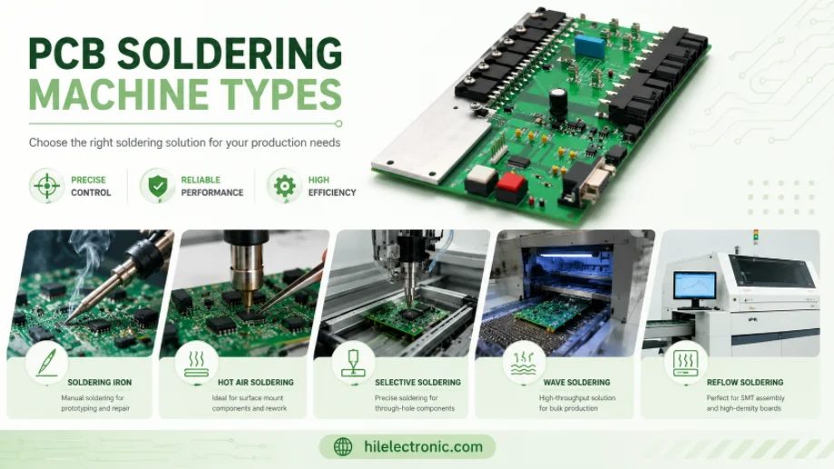
PCB Soldering Machine Types: Reflow, Wave, and Selective Equipment
Figure 1. PCB soldering machine types image for Highleap...
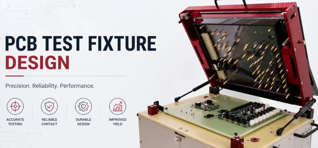
PCB Test Fixture Design: Bed-of-Nails, Flying Probe, and DFT
Figure 1. PCB test fixture design image for Highleap...
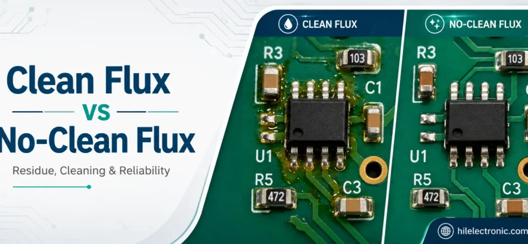
Clean Flux vs No-Clean Flux: Residue, Cleaning, and PCB Reliability
Figure 1. clean flux vs no-clean flux image for Highleap...
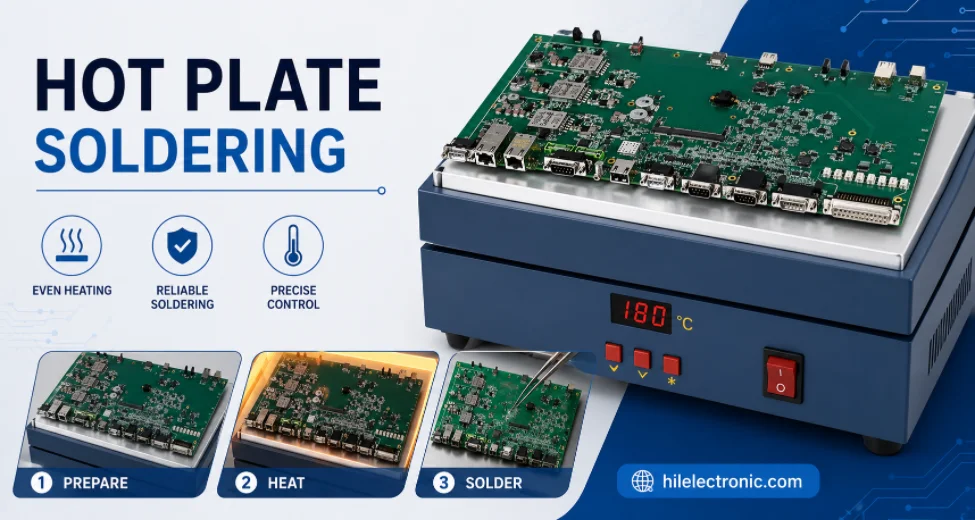
Hot Plate Soldering: Process, Limits, and Reflow Comparison
Figure 1. hot plate soldering image for Highleap...
How to get a quote for PCBs
Let‘s run DFM/DFA analysis for you and get back to you with a report. You can upload your files securely through our website. We require the following information in order to give you a quote:
-
- Gerber, ODB++, or .pcb, spec.
- BOM list if you require assembly
- Quantity
- Turn time
In addition to PCB manufacturing, we offer a comprehensive range of electronic services, including PCB design, PCBA, and turnkey solutions. Whether you need help with prototyping, design verification, component sourcing, or mass production, we provide end-to-end support to ensure your project’s success.
For PCBA services, please provide your BOM (Bill of Materials) and any specific assembly instructions. We also offer DFM/DFA analysis to optimize your designs for manufacturability and assembly, ensuring a smooth production process.