
PCB Lead Time and Turnaround Time Explained

PCB lead time directly impacts project schedules, yet many engineers underestimate the time required for quality fabrication. Understanding what drives manufacturing timelines helps set realistic expectations and identify opportunities to accelerate delivery when needed.
Table of Contents
At Highleap Electronics, we understand that lead time affects more than just delivery—it impacts your entire project schedule. This guide explains what determines PCB manufacturing time and how to optimize your timelines.
1. Standard PCB Lead Times by Type
PCB lead times vary significantly based on board complexity and order type. Understanding standard timelines helps with project planning.
1.1 Prototype Lead Times
Prototype orders prioritize speed over economy:
- 2-layer standard: 3-5 days
- 4-layer standard: 5-7 days
- 6-layer standard: 7-10 days
- 8+ layer: 10-15 days
These timelines assume standard specifications. Advanced features extend lead times accordingly.
1.2 Production Lead Times
Production orders balance cost and schedule:
- 2-layer standard: 7-10 days
- 4-layer standard: 10-14 days
- 6-layer standard: 12-18 days
- 8+ layer: 15-25 days
Larger quantities may extend timelines due to processing volume.
1.3 Quick-Turn Options
When schedules demand faster delivery:
- 24-hour: 2-layer only, significant premium
- 48-hour: Up to 4-layer, standard features
- 72-hour: Up to 6-layer, most features
- 5-day express: Most constructions, moderate premium
For urgent projects, see our expedited PCB manufacturing options.
1.4 Lead Time Starting Point
Lead time typically begins after complete data package received (Gerbers, drill files, fab drawing), any questions resolved, order confirmation and payment or credit approval, and materials in stock or ordered.
Incomplete data or pending questions delay the start of manufacturing.
2. Fabrication Process Timeline
Understanding the manufacturing sequence helps explain why certain lead times are necessary.
2.1 Pre-Production (1-2 days)
- Data review: Engineering checks files for manufacturability
- CAM processing: Files prepared for production equipment
- Material preparation: Laminate cut to panel size
- Tooling setup: Drill programs, imaging files prepared
2.2 Inner Layer Processing (1-2 days)
For multilayer boards:
- Imaging: Circuit pattern transferred to copper
- Etching: Unwanted copper removed
- AOI: Automated inspection of patterns
- Oxide treatment: Surface preparation for lamination
2.3 Lamination (0.5-1 day)
- Layup: Layers stacked with prepreg
- Press cycle: Heat and pressure bond layers
- Cooling: Controlled temperature reduction
2.4 Drilling (0.5-1 day)
- Through-hole drilling: Mechanical drilling of vias and holes
- Laser drilling: For microvias (if required)
- Hole inspection: Verification of hole quality
2.5 Plating and Outer Layer (1-2 days)
- Electroless copper: Seed layer for plating
- Pattern plating: Copper buildup on circuit pattern
- Tin plating: Etch resist
- Etching: Remove unwanted copper
- Tin strip: Remove etch resist
2.6 Finishing (1-2 days)
- Solder mask: Apply and cure protective coating
- Legend: Silkscreen component markings
- Surface finish: Apply final solderable surface
- Routing: Separate individual boards from panel
2.7 Final Processing (0.5-1 day)
- Electrical test: Verify continuity and isolation
- Final inspection: Visual and dimensional checks
- Packaging: Vacuum seal for protection

3. Factors That Extend Lead Time
Certain specifications and conditions add time to standard schedules.
3.1 Design Complexity
- High layer count: Each layer pair adds lamination cycles
- Blind/buried vias: Require sequential lamination
- HDI structures: Multiple lamination and laser drilling steps
- Fine features: Slower processing, more inspection
3.2 Material Factors
- Non-stock materials: Ordering adds 3-7 days typically
- Specialty laminates: May have processing differences
- Controlled dielectric: Material selection and verification
- Heavy copper: Slower etching processes
3.3 Process Requirements
- Impedance control: Requires test coupons and verification
- IPC Class 3: Additional inspection points
- Special testing: Hi-pot, TDR, microsection
- Tight tolerances: More careful processing
3.4 External Factors
- Data issues: Questions delay production start
- Holidays: Factory closures affect schedule
- Capacity: High demand periods extend lead times
- Quality escapes: Rework extends delivery
4. Strategies for Reducing Lead Time
Practical approaches to minimize PCB delivery time without compromising quality.
4.1 Design for Speed
- Minimize layers: Fewer layers = fewer process steps
- Use standard features: Non-standard features require special handling
- Avoid exotic materials: Stock materials ship faster
- Specify realistic tolerances: Tight tolerances slow processing
4.2 Data Preparation
- Complete packages: Include all required files first time
- Clear documentation: Minimize engineering questions
- DFM check: Verify manufacturability before ordering
- Accurate BOM: For assembly projects, prevent sourcing delays
4.3 Supplier Relationship
- Forecast demand: Alert supplier to upcoming orders
- Stock materials: Pre-position specialty materials
- Established programs: Repeat orders process faster
- Communication: Quick responses keep projects moving
4.4 Parallel Processing
- Order PCB early: Don’t wait for final BOM completion
- Source components: Start procurement parallel to PCB fabrication
- Prepare assembly: Have assembly partner ready when boards arrive
For projects including assembly, plan for PCB assembly lead time in addition to fabrication.

5. Expedited Options and Trade-offs
When standard lead times don’t meet schedule requirements, expedited options exist—with trade-offs.
5.1 Quick-Turn Services
Expedited PCB manufacturing compresses schedules through priority scheduling, dedicated processing, overtime labor, and reduced batching.
5.2 Cost Premiums
Expedite charges typically scale with urgency:
- 5-day (vs. 10-day standard): 25-50% premium
- 3-day: 50-100% premium
- 48-hour: 100-150% premium
- 24-hour: 150-250% premium
Premiums apply to PCB fabrication cost base—complex boards with high base costs see larger absolute increases.
5.3 Capability Limitations
Not all specifications support extreme expedition:
- 24-hour: 2-layer, standard features only
- 48-hour: Up to 4-layer, limited features
- 72-hour: Up to 6-layer, most features
Complex multilayer and HDI require minimum processing times regardless of urgency.
5.4 Quality Considerations
Rushing production increases risk. Reputable manufacturers maintain quality standards but may limit expedition options rather than compromise quality. Don’t sacrifice quality for speed—field failures cost more than schedule delays.
6. Planning for Predictable Delivery
Proactive planning eliminates most lead time challenges.
6.1 Realistic Scheduling
Build realistic timelines using standard lead times plus contingency. Standard prototype: 7-10 days, add 3-5 days contingency. Standard production: 14-21 days, add 5-7 days contingency. First-time builds: Add extra time for potential issues.
6.2 Critical Path Awareness
Identify what’s actually time-critical. Often, assembly and test are longer than PCB fabrication. Component lead times frequently exceed board lead times. Don’t rush PCB fabrication if components won’t arrive for weeks.
6.3 Supplier Communication
Keep your manufacturer informed about upcoming projects and volume forecasts, schedule-critical orders, potential design changes, and any special requirements.
Highleap Electronics provides lead time estimates during quoting, updates during production, and proactive communication if issues arise.
6.4 For Assembly Projects
If your project includes assembly, total lead time includes PCB fabrication, component sourcing (often the longest element), PCB assembly lead time, and testing and shipping.
For urgent complete assemblies, see our quick turn PCBA lead time options.
Contact our team to discuss your timeline requirements and develop a realistic production schedule for your project.

Recommended Posts
TUC TU-862 HF PCB Manufacturing and Assembly Service
Table of contentsWhat Is TU-862 HF?Why Choose TU-862 HF...
Shengyi S7136H PCB Manufacturing and Assembly Service
Table of contentsWhat Is a Shengyi S7136H PCB?Why...
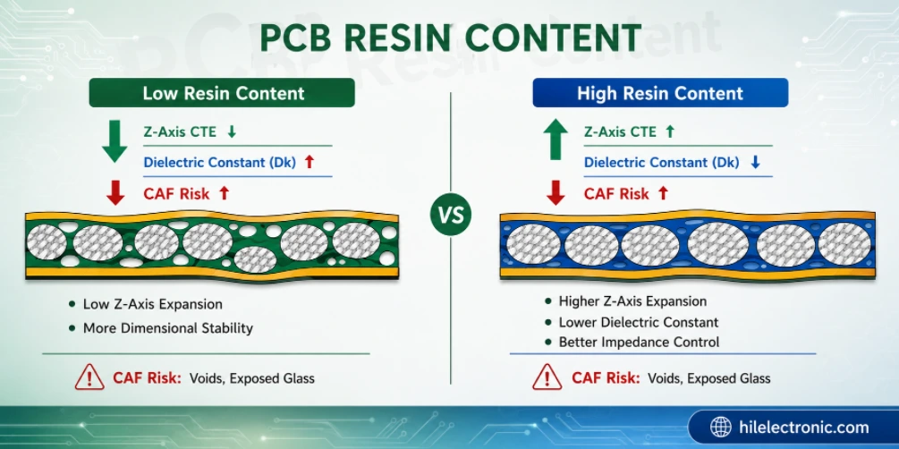
PCB Resin Content: Stackup, Lamination and Manufacturing Guide
Table of contentsWhat PCB Resin Content MeansHow Resin...
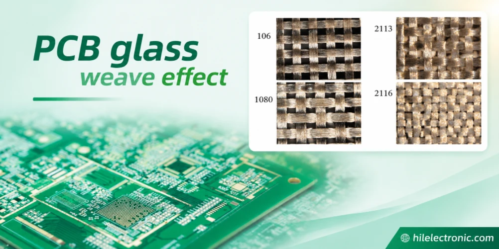
PCB Glass Weave Effect: Design, Material and Manufacturing Control
Table of contentsWhat Causes PCB Glass Weave Effect?When...
How to get a quote for PCBs
Let us run DFM/DFA analysis for you and get back to you with a report.
You can upload your files securely through our website.
We require the following information in order to give you a quote:
-
- Gerber, ODB++, or .pcb, spec.
- BOM list if you require assembly
- Quantity
- Turn time
In addition to PCB manufacturing, we offer a comprehensive range of electronic services, including PCB design, PCBA (Printed Circuit Board Assembly), and turnkey solutions. Whether you need help with prototyping, design verification, component sourcing, or mass production, we provide end-to-end support to ensure your project’s success. For PCBA services, please provide your BOM (Bill of Materials) and any specific assembly instructions. We also offer DFM/DFA analysis to optimize your designs for manufacturability and assembly, ensuring a smooth production process.