
Reliable PCB Assembly Solutions Tailored to Your Needs

A circuit board can be difficult to assemble even when the PCB itself has been manufactured correctly. In practice, many production issues come from the details around the board: a footprint that does not match the selected component, an outdated Pick-and-Place file, a last-minute BOM substitution, insufficient solder paste on a bottom-terminated package, or a test requirement that was never included in the original build data. We review these items together before production because they affect yield, rework and the time it takes to get a new assembly running consistently.
Highleap supports circuit board assembly from prototype and NPI builds through low-volume and production orders. Our work can include PCB fabrication, component sourcing, SMT and through-hole assembly, BGA and fine-pitch components, AOI and X-ray inspection, programming, functional testing and final product integration. Our PCBA facility operates five SMT placement lines with published capacity of up to 10,000,000 component placements per day, giving us the flexibility to handle engineering builds as well as programs that later move into sustained production.
Table of contents
- Circuit board assembly capabilities
- What to send for a PCBA quote
- How we build your circuit boards
- SMT, through-hole and BGA assembly
- How we inspect and test a PCBA
- Turnkey component sourcing and BOM control
- From prototype to repeat production
- Programming, coating and box build
- Why work with Highleap?
- Circuit board assembly FAQ
Circuit Board Assembly Capabilities
The specification of the board determines far more than whether it runs on an SMT or through-hole line. Component size, package style, PCB construction, solder process, board rigidity, inspection access and expected production quantity all affect how the assembly should be prepared. We therefore confirm capability against the actual Gerber or ODB++ data, BOM and component packages rather than approving a project from a component count alone.
- Prototype to Production: We support engineering prototypes, NPI builds, low-volume runs and repeat manufacturing. For established products that need larger, scheduled production lots, our high-volume PCB assembly capability provides a path to scale without moving the project to a different assembly supplier.
- SMT Production: Highleap operates five SMT placement lines with published placement capacity of up to 10,000,000 components per day. The same production environment can accommodate conventional SMD assemblies as well as boards containing smaller and more demanding packages.
- Component Packages: Standard published capability includes components down to 0201 together with BGA, QFN, QFP, CSP and other commonly used surface-mount packages. Boards with unusually tight pitch or non-standard packages are checked individually before production.
- BGA Assembly: Our published standard capability includes a minimum BGA pad diameter of 0.20 mm, while 0.15 mm can be evaluated for prototype work after engineering review. BGA manufacturability is checked together with pad geometry, solder mask, via structure and package requirements rather than by pitch alone.
- Through-Hole and Mixed Assembly: Connectors, relays, transformers, terminal blocks, power components and other through-hole devices can be combined with SMT on the same PCBA. The soldering sequence is selected according to the board layout, component mix and thermal requirements.
- Rigid, Flex and Rigid-Flex Boards: Assembly is not limited to conventional rigid PCBs. We also support flex PCB assembly and rigid-flex designs where substrate support, handling during placement and reflow, and fixture design need additional attention.
- Lead-Free and Leaded Processes: Both solder systems are available. The required process should be identified in the production documentation because solder alloy and component requirements affect the reflow profile and downstream soldering operations.
- Inspection and Test: Depending on the board, the production plan can include solder paste inspection, AOI, visual inspection, X-ray, electrical verification and functional testing. A BGA-heavy board, for example, requires a different inspection approach from an assembly made primarily with components that have visible leads.
- Post-Assembly Operations: IC programming, conformal coating, potting, mechanical assembly and box build can be incorporated when the required deliverable is a tested subassembly or more complete electronic product rather than a loose PCBA.
These capabilities describe the normal range of work handled by our PCBA operation, but they are not a substitute for reviewing the actual design. Boards with unusually fine-pitch components, high thermal mass, flexible sections, special solder alloys or non-standard inspection requirements are checked against the production files before the process is confirmed.
For customers that prefer one supplier to manage the complete build, our turnkey PCB assembly service combines bare-board manufacturing, component procurement, assembly, inspection and testing under one project.
What to Send for a PCBA Quote
A good quotation starts with manufacturing data that agrees with itself. One of the easiest ways to create an avoidable assembly problem is to send the Gerber files from one revision, a BOM from another revision and an older Pick-and-Place file. Each document may look correct on its own while the complete package is wrong.
For the first engineering review, we normally need the following information:
- Gerber or ODB++ Data: Send the production data for the PCB revision that will actually be assembled. This should include the copper layers, solder mask, silkscreen, drill files, board outline and relevant mechanical information.
- Bill of Materials: The BOM should include reference designators, quantities, manufacturer names, exact manufacturer part numbers, values or descriptions, package information and DNP/DNI status where applicable.
- Pick-and-Place File: The placement file normally contains the reference designator, X/Y location, rotation and board side for each automatically placed component.
- Assembly Drawing: This is particularly useful for polarized parts, unusual connectors, mechanical hardware, wires, components fitted after soldering and parts that must intentionally remain unpopulated.
- Required Quantity: Prototype, NPI and production quantities may use different material, setup and test strategies, so the expected build quantity should be stated at quotation.
- Programming Requirements: If an MCU, memory device, FPGA or other programmable component needs firmware, include the device information, programming file and revision.
- Functional Test Requirements: Where the finished board must be powered and tested, provide the operating conditions, expected behavior and pass/fail criteria as early as possible.
Customers often ask whether a rough quote can be prepared from partial data. In many cases it can, but a production-ready quotation still needs the actual component list and board files. The more accurately the data represents the product being built, the fewer assumptions have to be made during engineering review.
How We Build Your Circuit Boards
There is no single assembly route that fits every PCBA. A double-sided board with several BGAs requires different process decisions from a power-control board containing large connectors, relays and through-hole components. The sequence below describes the normal manufacturing logic, but individual boards may add or rearrange operations.
- Engineering Review: PCB data, BOM, placement files and special instructions are checked together. The purpose is to identify issues such as package mismatches, unclear polarity, difficult component spacing, unsuitable panelization or missing manufacturing information before material reaches the line.
- Material Preparation: Bare boards and components are prepared against the approved build package. Customer-supplied components should be clearly labeled, and moisture-sensitive devices need to be stored and handled according to their requirements.
- Stencil and Solder Paste Printing: SMT pads receive solder paste through a production stencil. Fine-pitch devices, thermal pads and very small passive parts may require aperture adjustments rather than simply reproducing the copper-pad geometry at a one-to-one ratio.
- Automated Placement: Placement equipment installs the SMT parts according to approved coordinates and rotations. Orientation control is particularly important for ICs, diodes, LEDs, polarized capacitors and connectors.
- Reflow: The populated board passes through a controlled temperature profile. PCB thickness, copper distribution, solder alloy and component thermal mass all influence how the board heats and cools.
- Inspection: After reflow, AOI can inspect visible placement and soldering conditions. Boards containing BGA or other bottom-terminated packages can move to X-ray where hidden joints need to be evaluated.
- Through-Hole and Secondary Assembly: Relays, terminal blocks, transformers, connectors, heat sinks and other secondary parts are installed at the appropriate stage rather than forcing every component through the SMT process.
- Programming and Testing: Firmware loading, electrical verification and functional testing are added according to the build documentation.
- Finishing: Where required, the completed PCBA can proceed to cleaning, conformal coating, potting, mechanical assembly, labeling and final packaging.
The SMT portion of this flow is covered in more detail on our surface mount technology page. On this page, the more important point is how SMT fits into the complete PCBA process rather than explaining every machine operation in isolation.
SMT, Through-Hole and BGA Assembly
Most practical circuit board assemblies are mixed. A controller may use SMT for processors and passive parts, BGA for a high-I/O device and through-hole mounting for relays, power connectors or field terminals. The manufacturing challenge is not simply having all three capabilities; it is selecting a sequence that protects the parts already on the board while the remaining operations are completed.
- SMT Assembly: Surface mount technology handles most resistors, capacitors, ICs and compact packages. Paste volume, placement accuracy and the reflow profile become increasingly important as components become smaller or pad spacing becomes tighter.
- Through-Hole Assembly: THT remains useful for parts that need additional mechanical support or are physically unsuitable for normal SMT placement. Depending on the board, soldering may be completed by wave soldering, selective soldering or controlled manual processes.
- Mixed Technology: When SMT and through-hole parts share the same board, the process has to account for subsequent solder cycles, selective-solder access, component height and heat-sensitive devices.
- BGA Assembly: The solder connections beneath a BGA are not visible from the outside. Good BGA assembly therefore depends on the PCB footprint, solder mask, via design, solder paste volume, package condition, placement and reflow working together.
- QFN and Other Bottom-Terminated Packages: Thermal-pad geometry and paste control matter because a large portion of the solder joint is underneath the package rather than visible around the edge.
If a design contains an unusual BGA, QFN, CSP or another fine-pitch device, include the exact manufacturer part number when requesting the quote. The mechanical drawing in the component datasheet tells an assembly engineer much more than a generic BOM entry such as “BGA processor.”
For rigid-flex products, the assembly review also considers how the flexible areas will be supported during printing, placement and handling. The underlying construction is covered separately on our rigid-flex PCB fabrication page.

How We Inspect and Test a PCBA
“100% inspection” sounds reassuring, but it does not explain what was actually inspected. No single method can see every defect. AOI can check visible placement and soldering features, X-ray can examine joints hidden beneath packages, and a functional test can determine whether the assembled circuit operates correctly when powered. Those methods answer different questions.
- Solder Paste Inspection: SPI is used where control of solder-paste position and volume is important. Finding a printing issue before components have been placed and reflowed is usually much easier than repairing the assembly later.
- Automated Optical Inspection: AOI can detect visible problems such as missing components, incorrect placement, polarity errors, alignment issues and certain solder defects.
- X-Ray Inspection: X-ray is particularly useful for BGA and other packages where critical solder joints are hidden. It can help evaluate bridging, abnormal solder distribution, voiding and package alignment.
- Electrical Verification: Electrical checks can identify shorts, opens or other conditions that may not be obvious through visual inspection alone.
- Functional Testing: A board may look correct and still fail in operation. Depending on the product, FCT can verify power rails, current consumption, I/O behavior, communication interfaces, relays, sensors, displays and firmware operation.
Functional testing is most effective when the acceptance criteria are defined before production. “The board works normally” is difficult to turn into a repeatable production test; voltage limits, current ranges, expected interface responses and explicit pass/fail conditions are much more useful.
For boards that need powered verification, see our PCBA functional testing service. Broader information about inspection and manufacturing controls is available on our PCB quality page.
Turnkey Component Sourcing and BOM Control
Component procurement is closely connected to assembly. Buying the right quantity is not enough; the part has to match the electrical requirement, package, footprint and approved revision. This becomes especially important when a component is obsolete, allocated or offered with several similar package options.
For turnkey projects, our electronic component sourcing process works from the approved BOM and exact manufacturer part numbers wherever those numbers are available.
- Exact Part Identification: Manufacturer part numbers are preferred over generic descriptions because they define the package and electrical characteristics more clearly.
- Approved Alternatives: A substitute should be reviewed before purchase. Package dimensions, pinout, thermal pad, height, voltage rating and process limitations can make an apparently similar part unsuitable.
- Customer Approval: Where the specified component has to be replaced, the substitute and any relevant impact on assembly should be agreed before it is released to production.
- Consigned Components: Customers can supply all components or only selected critical parts. This is common for proprietary devices, pre-programmed parts and material that has already been purchased.
- Material Traceability: Component labels, lot information and controlled BOM revisions help production identify exactly which material belongs to a build.
One common source of unnecessary rework is treating a component change as a purchasing decision only. If the replacement package or pinout changes, the PCB, placement data, programming process or test method may also need to change. The BOM therefore has to stay connected to the complete manufacturing package.
From Prototype to Repeat Production
A prototype build and a production build have different priorities. During an early engineering run, finding a problem is useful because the design can still be corrected at relatively low cost. Once the product moves into repeat production, the objective shifts toward process stability, controlled revisions and consistent output from lot to lot.
- Prototype Builds: Early PCBAs help verify footprint accuracy, component fit, connector position, programming, thermal behavior, functional operation and basic manufacturability.
- NPI: New product introduction is where the engineering files begin to become a controlled production package. Questions found here should be resolved before purchasing larger component quantities.
- Low-Volume Production: Smaller runs are useful for specialized equipment, engineering validation and products whose demand does not justify immediate high-volume production. More detail is available on our low-volume PCB manufacturing and assembly page.
- Repeat Production: Once the design is stable, PCB revision, BOM revision, assembly drawing, firmware, approved alternatives and test procedure should be controlled together.
- Engineering Changes: When one item changes, the effect on the rest of the manufacturing package should be checked. A new component may change the footprint; new firmware may change the functional test; a new connector may affect the mechanical assembly.
This transition is easier when prototype builds already use production-quality files and clear acceptance criteria. The goal is not merely to make the first few boards work; it is to learn what needs to be controlled before the same product is built repeatedly.

Programming, Coating and Box Build
For many electronic products, component soldering is only part of the finished manufacturing flow. A PCBA may still need firmware, environmental protection, cables, an enclosure, heat sinks or final system testing before it is ready to ship.
- IC Programming: Supported MCU, memory and programmable devices can be programmed using offline or in-circuit methods depending on the component and production requirement. See our IC programming service for supported workflows.
- Firmware Revision Control: Programming files should be released with a clear version. Changing firmware without updating the build documentation creates the same type of traceability problem as changing the BOM without changing its revision.
- Conformal Coating: Boards used in humid, dusty or chemically aggressive environments may require protection after assembly and testing. Our conformal coating process supports selective coating where keep-out areas, connectors and test points are defined in the production documentation.
- Potting: Where encapsulation is required, the choice of material and coverage depends on the product’s mechanical, environmental and thermal requirements.
- Mechanical Integration: Heat sinks, cables, displays, switches and other mechanical components can be added after the electronic assembly is complete.
- Box Build: Projects that need a more complete unit can continue into box build assembly, including enclosure integration, cable installation, firmware loading, final testing, labeling and packaging.
These operations should be discussed during quotation rather than added after the PCBA is complete. Coating keep-out areas, programming access, test connectors and mechanical clearances can all influence the board or assembly documentation.
Why Work with Highleap for Circuit Board Assembly?
The basic mechanics of PCB assembly are widely available. The harder part for an OEM is keeping board fabrication, component procurement, assembly, programming, testing and product revisions aligned when a project changes. That is where having the PCB and PCBA processes under one manufacturing organization becomes useful.
- PCB Fabrication and PCBA Are Connected: If an assembly issue originates in the bare board — pad geometry, solder mask, panelization, via construction or finish — the question can be reviewed with the fabrication process rather than passed between unrelated suppliers.
- Real Production Capacity: Highleap’s published factory information includes five SMT placement lines and SMT capacity of up to 10,000,000 component placements per day, together with dedicated through-hole capability and downstream assembly processes.
- Engineering Review Before Production: Package mismatches, component substitutions and revision problems are more useful when they are found before material reaches the line. Our manufacturing workflow therefore starts with the production data rather than with the placement machine.
- Inspection Matches the Board: A board with exposed gull-wing leads does not need exactly the same inspection strategy as a BGA-heavy assembly. AOI, X-ray and functional testing are selected for what actually needs to be verified.
- Turnkey and Consigned Options: We can manage the complete BOM or work with customer-supplied parts, allowing the supply model to match the way the customer controls critical material.
- Support Beyond Assembly: Programming, conformal coating, mechanical integration and final box build can remain part of the same project when the required deliverable is a tested subassembly or finished electronic unit.
Customers evaluating a new supplier can review our PCB and PCBA manufacturing operations, factory information and quality-management background before sending production files.

Circuit Board Assembly FAQ
What is circuit board assembly?
Circuit board assembly is the manufacturing process of installing and soldering electronic components onto a bare printed circuit board. The completed populated board is generally called a PCBA, or printed circuit board assembly.
What is the difference between a PCB and a PCBA?
A PCB is the bare circuit board before components are installed. A PCBA is the board after the required components have been mounted, soldered and, where required, programmed and tested.
What files do I need for a circuit board assembly quote?
For most projects, send Gerber or ODB++ files, the BOM, Pick-and-Place data, required quantity and an assembly drawing if one is available. Include firmware, functional-test instructions, coating requirements or mechanical information when those operations are part of the build.
Can Highleap manufacture the bare PCB and assemble it?
Yes. PCB fabrication and circuit board assembly can be combined in one manufacturing project. Customers can also provide their own PCBs or components for partial-turnkey and consigned assembly.
Can Highleap source the electronic components?
Yes. Component procurement can be included in a turnkey build. Exact manufacturer part numbers are preferred, and approved alternatives should be identified where substitutions are permitted.
Can you assemble BGA and QFN components?
Yes. BGA, QFN and other fine-pitch or bottom-terminated packages are supported subject to engineering review. X-ray inspection can be included where the solder connections cannot be adequately inspected from the board surface.
What is the smallest component size you support?
Highleap’s published standard PCBA capability includes 0201 components. Actual manufacturability still depends on the PCB footprint, solder mask, stencil, component spacing and surrounding layout.
Do you provide through-hole assembly?
Yes. Through-hole and mixed-technology assemblies are supported. The soldering method is selected according to component type, board layout and production quantity.
Can firmware be programmed during assembly?
Yes. Programming can be integrated into production for supported devices when the correct firmware file, revision and programming instructions are supplied.
Do you provide functional testing?
Yes. Functional testing can be performed according to customer-defined operating requirements and pass/fail criteria. Projects requiring a custom fixture or test software should define those requirements before production.
Can you apply conformal coating?
Yes. Conformal coating can be incorporated after assembly and testing. The customer should identify coating material requirements, masking areas, connectors and test points that must remain uncoated.
Can you build the complete electronic product?
Yes. Where required, a project can continue from PCBA into programming, cable installation, mechanical integration, enclosure assembly, final functional testing and packaging.
Get a Free PCB & PCBA Quote
Recommended Posts

HDI PCB Assembly | One-Stop HDI PCB Service
Figure 1. HDI PCB Assembly with Black Solder MaskHDI PCB...
Contract Manufacturing Transfer Without PCBA Supply Disruption
Table of contents Why PCB Assembly Transfers Fail The...
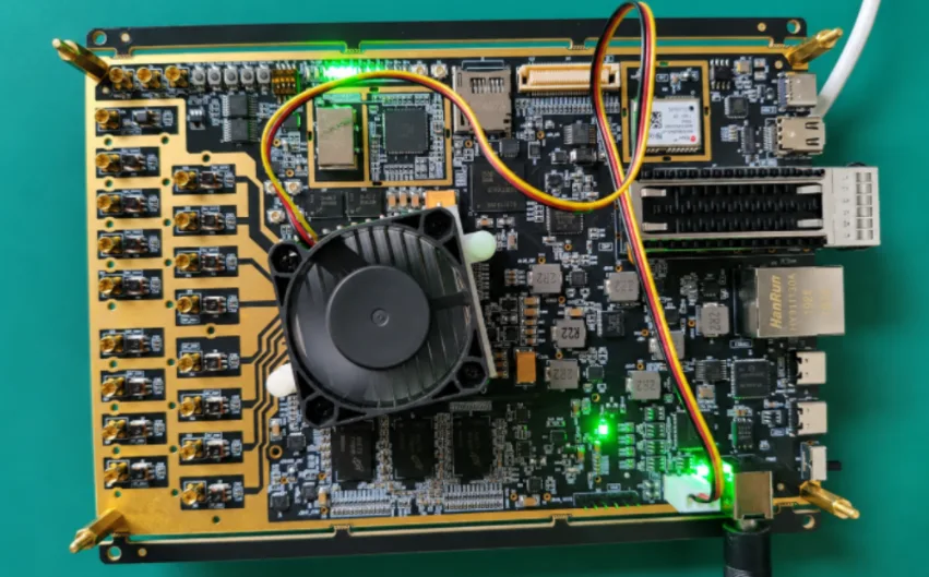
RFSoC Board PCB Manufacturing and Assembly One-Stop Service
Table of contentsReference RFSOC Board Project: 115 × 175...
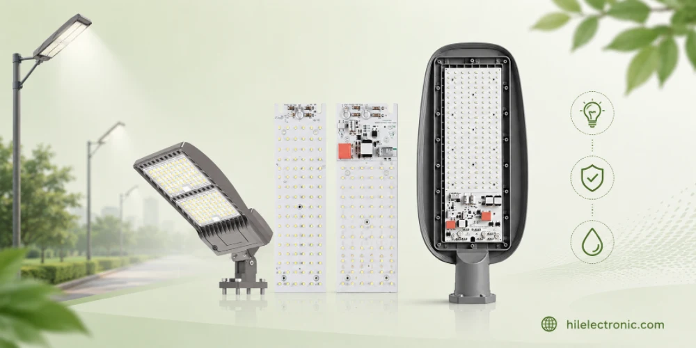
Outdoor Lighting PCB Manufacturing & Assembly by Highleap Electronics
Figure 1. outdoor lighting PCB production and assembly...
How to get a quote for PCBs
Let us run DFM/DFA analysis for you and get back to you with a report.
You can upload your files securely through our website.
We require the following information in order to give you a quote:
-
- Gerber, ODB++, or .pcb, spec.
- BOM list if you require assembly
- Quantity
- Turn time
In addition to PCB manufacturing, we offer a comprehensive range of electronic services, including PCB design, PCBA (Printed Circuit Board Assembly), and turnkey solutions. Whether you need help with prototyping, design verification, component sourcing, or mass production, we provide end-to-end support to ensure your project’s success. For PCBA services, please provide your BOM (Bill of Materials) and any specific assembly instructions. We also offer DFM/DFA analysis to optimize your designs for manufacturability and assembly, ensuring a smooth production process.