
FPC PCB Design Guide for Flexible Printed Circuits

Flexible Printed Circuits (FPCs), also known as flexible circuit boards, are an essential component in modern electronics. These circuit boards utilize flexible materials such as polyimide or polyester films as substrates, enabling designs that can be bent, twisted, or folded without compromising their electrical performance. With advantages like high wiring density, lightweight construction, and reduced thickness, FPCs are used in a variety of applications ranging from consumer electronics to aerospace. This article offers a thorough introduction to the principles of FPC PCB Design, including material selection, circuit design, key design considerations, and cost-saving strategies.
1. Material Selection for FPCs
The material selection is crucial to the performance and reliability of an FPC PCB Design. The right materials ensure that the circuit can perform under specific mechanical, thermal, and electrical conditions. The following materials are typically used for different components in FPC PCB Design:
1.1 Substrate Materials
- Polyimide Film: Known for its excellent thermal stability, flexibility, and electrical insulation properties, polyimide is the most commonly used substrate material for FPCs. It can withstand temperatures up to 250°C, making it ideal for demanding applications.
- Polyester Film: A more cost-effective alternative to polyimide, polyester is often used in low-cost applications. While it offers less heat resistance and flexibility than polyimide, it is still suitable for many consumer electronics.
1.2 Copper Materials
- Electrolytic Copper (18/12.5 Double-Sided): This material is commonly used for the conductive layers in FPCs. It provides an excellent balance between conductivity and flexibility, making it ideal for applications such as side keys, main buttons, and connecting wires.
- Copper-Free Materials: Some specialized FPCs may require copper-free conductive materials, especially when flexibility and weight savings are critical.
1.3 Conductive Materials
- Conductive Adhesive Tapes: These are used for bonding conductive areas where traditional soldering is not feasible. High-conductivity adhesive tapes are typically employed in sensitive components like special keypads, though their high cost limits their use in mass production.
- Conductive Cloth & Pure Glue: While conductive cloth offers good conductivity, it lacks strong adhesive properties. Conductive pure glue is a high-strength option but is expensive and generally not recommended unless absolutely necessary.
1.4 Reinforcement Materials
- PI Reinforcement (Polyimide): This is used to strengthen areas subject to mechanical stress, particularly for plug-in boards with finger connectors. It is strong but expensive, making it ideal only for critical reinforcement.
- FR-4 Reinforcement: This fiberglass-based material is commonly used to reinforce keypads and side keys. It provides strong mechanical support but must be bonded with pure glue for maximum effectiveness.
2. Key Considerations in FPC Design
FPC design involves a series of important decisions that impact the circuit’s functionality, reliability, and cost. These considerations must be accounted for during the early stages of design to avoid issues during manufacturing and usage.
2.1 Flexibility Considerations
- Via Placement: Avoid placing vias in bending or sliding areas, as they can weaken the structure and cause failure during flexing. Vias should be located outside of these sensitive zones to prevent stress concentrations.
- Grounding Holes: Grounding holes should also be positioned outside of the bending area. Misplacement can affect the FPC’s performance, especially if the FPC is subjected to frequent movement.
2.2 Mechanical Strength
- Reinforcement Selection: The use of appropriate reinforcement materials, such as PI or FR-4, in areas subject to high mechanical stress (e.g., connectors, plug-in positions) is essential. Reinforcement provides structural integrity while maintaining the flexibility of the FPC.
- Bending Radius: The bending radius of an FPC should be carefully calculated to avoid stress points. Sharp bends or excessive curvatures can lead to electrical failures or physical damage.
2.3 Via Design for Reliability
- Avoiding Stress Concentration: Vias should be placed in non-critical areas to avoid creating weak points that may fracture under mechanical stress. This is especially important in FPCs that will undergo repeated bending or dynamic movement.
2.4 Thermal Management
- Heat Resistance: FPCs are often exposed to high temperatures, making material selection crucial for thermal management. Polyimide is preferred in high-temperature environments due to its thermal stability, while polyester is better suited for lower-temperature applications.

3. FPC Circuit Design: In-Depth Principles and Best Practices
The circuit design on a FPC is not only a technical challenge but also a critical factor that determines the overall performance and reliability of the final product. FPCs combine the flexibility of the substrate with precise electrical connectivity, making it essential to balance factors such as electrical conductivity, manufacturability, and mechanical durability. Below are comprehensive and highly detailed principles to guide the FPC circuit design process.
3.1 Key Design and Pad Layout
Key Pad Layout: In FPC designs that incorporate keypads, such as for mobile devices or control panels, the key pads must be designed with adequate size to ensure proper functioning. Specifically, the key pads should always be larger than the domes or contact sheets they actuate. The pad area needs to fully accommodate the dome’s footprint to ensure reliable mechanical actuation, avoiding scenarios where the domes may fail to contact the pads properly.
-
Domed Sheet Compatibility: The size of the key pads must correspond to the design and dimensions of the dome sheets, which create the tactile feedback when pressed. Therefore, the key pad must not only be large enough to trigger the dome but also allow for consistent and repeatable keypress actions.
-
Pad-to-Pad Distance: The distance between adjacent pads should follow strict industry standards (usually a gap between 0.25mm to 0.5mm) to ensure proper alignment, which is crucial for both assembly and soldering. Incorrect pad spacing can lead to misalignment during the manufacturing process or result in shorts or open circuits during operation.
Key Connections: The connections between the keypads and the rest of the circuit are critical to ensure the board operates efficiently and reliably. The trace width for these connections plays a significant role in both electrical conductivity and the mechanical resilience of the circuit.
-
Minimum Trace Width: The minimum width of traces connecting the keys should typically be 0.2mm or greater, depending on the current-carrying requirement of the trace. Smaller traces may be prone to overheating or failure, especially in designs that involve power supply or signal lines.
-
Smooth Transitions: For robust and reliable connections, the design of transitions between key connection traces and the pads should be smooth and gradual. This eliminates sharp angles or corners, which can act as stress concentrators and result in fracture points, especially during repeated bending or flexing of the FPC.
-
Key Placement and Alignment: Additionally, the keypads’ physical placement should allow enough clearance between pads to avoid unintentional short circuits. This is especially important in high-density designs where many traces and pads are packed into a small area.
3.2 Via Design
Via Placement in Bending Areas: Vias play a key role in multi-layered FPCs by connecting the various conductive layers. However, vias should never be placed in areas where the FPC will bend, as bending around vias can lead to catastrophic failure. The bending process causes stress at the via locations, which can result in cracking, delamination, or complete failure of the via over time.
-
Stress Concentration Risks: The integrity of the FPC can be compromised if vias are placed within bending zones. In flexible designs, the mechanical stresses induced by repeated bending can cause localized failures, especially at via holes, due to the cyclic expansion and contraction of the material. This is why placing vias in non-bending areas is critical for improving durability and reliability.
-
Alternate Via Designs: In areas where vias are absolutely necessary but must remain outside bending zones, engineers can explore options like blind vias or buried vias—these vias connect specific layers without puncturing the flexible areas.
Minimizing Via Count: While vias are necessary for multi-layer circuit designs, reducing their number can greatly improve the manufacturing process and overall FPC quality. Fewer vias reduce the chances of manufacturing defects and lead to fewer failure points in the flexible circuit. This not only optimizes cost but also simplifies the assembly process.
- Fewer Vias = Higher Yield: Reducing the total number of vias also contributes to higher yield rates during production. With fewer complex holes to drill and fill, the circuit’s overall reliability improves, and the possibility of defects such as unfilled vias or solder joint failure decreases.
3.3 Bendable Area Design
Soft Design for Bending Areas: One of the most important aspects of FPC design is ensuring that the board’s bending areas are flexible enough to handle repeated cycles of movement without damage. The bending area must be carefully designed to avoid stress concentration, which can cause physical damage or electrical failure.
-
Mesh Pattern or Copper Removal: In the bending area, the copper material can be either perforated into a mesh pattern or removed entirely. Perforating the copper in this way ensures that the FPC remains flexible without sacrificing the board’s electrical conductivity in non-bending areas. Alternatively, completely removing copper from the bend zone reduces the chances of copper cracking or delaminating during repeated bending.
-
Avoiding Copper Fracture: Copper is relatively brittle compared to the flexible polyimide substrate, and excessive copper in bending areas can lead to fractures, especially in smaller traces. By strategically removing copper, engineers ensure that these areas can flex repeatedly without causing damage to the circuit itself.
Bending Radius: The bending radius plays a crucial role in the FPC’s durability. The board should have a well-defined minimum bending radius to avoid excessive mechanical strain on the material.
-
Recommended Bending Radius: The radius of the bend should be at least 10 times the thickness of the FPC. A larger bending radius ensures that the FPC does not undergo excessive stretching or compression, preventing damage to the circuit or conductive traces.
-
Strain Reduction through Flexible Design: By creating flexible traces that can expand and contract within the bending area, the circuit can endure multiple flexing cycles. Additionally, any additional mechanical features such as reinforcement or over-molding should be incorporated to enhance the FPC’s overall resilience.
Preventing Delamination: During flexing, if the copper and polyimide layers of the FPC are not properly bonded, delamination may occur. This is particularly problematic in areas subjected to repeated bending, as the stresses may cause the layers to separate over time.
- Adhesion and Bonding: To prevent delamination, the adhesive layer between the copper foil and the polyimide substrate must be of high quality. Polyimide-based adhesives with high-temperature resistance are commonly used for their strong bond, ensuring that the copper layer stays intact even under flexing conditions.
Designing FPC circuits involves considering a variety of factors that go beyond simple electrical functionality. Key considerations such as via placement, key pad layout, and bending area design all contribute to the overall durability, reliability, and performance of the final FPC. Engineers must strike a balance between electrical requirements and the mechanical properties of the board, ensuring the FPC can withstand repeated flexing and stress without compromising its integrity. By following these detailed principles, designers can ensure that their FPCs deliver optimal performance across a wide range of applications while minimizing the risks of mechanical failure or electrical disconnects.

4. Cost Optimization and Quality Enhancement in FPC Design
When designing Flexible Printed Circuits (FPCs), balancing cost and quality is crucial for achieving an efficient and competitive product. Ensuring the quality of the final FPC while optimizing costs involves a strategic approach to material selection, design choices, and manufacturing processes. Below are key strategies to optimize both cost and quality.
Use this page for FPC design choices: bend radius, copper type, stiffeners, coverlay, and assembly constraints. For sourcing and production capability, review flex circuit manufacturing service; for layer buildup and routing density, use multilayer flexible circuits and Highleap’s flex PCB manufacturing.
4.1 Cost Optimization
Standardization of Components: One of the most effective ways to reduce costs in FPC design is through the standardization of components. By using commonly available and standardized shapes for reinforcement materials, adhesive tapes, and other elements, manufacturers can avoid the additional costs associated with custom tooling and production processes.
-
- Standardizing Reinforcements and Tapes: Standard reinforcement and adhesive tape sizes not only streamline the design process but also reduce the need for specialized production tools. This can lead to a significant reduction in both material and tooling costs, which is especially beneficial for large-volume production.
- Avoiding Custom Designs: Custom shapes or non-standard materials should be minimized unless absolutely necessary for meeting specific functional or mechanical requirements. Custom tooling often incurs higher setup costs, longer lead times, and greater complexity in the production process, which increases the overall unit cost.
Material Utilization Efficiency: Efficient use of materials is another key strategy for cost optimization. The goal is to minimize material waste while maintaining the quality and functionality of the FPC. Proper material selection and design choices can result in significant savings.
-
- Layer Optimization: Reducing the number of layers in the FPC when possible is one of the most effective ways to cut costs. For example, opting for a four-layer design instead of a five-layer design can reduce both material costs and processing time without compromising performance, especially in less demanding applications.
- Minimizing Non-Essential Material Usage: Areas of the FPC that are not critical to the functionality—such as specific portions of the bending zones or unused spaces—can be designed to remove unnecessary copper or insulation. This helps reduce material waste and lower production costs.
Reducing Manufacturing Steps: Reducing the complexity of the manufacturing process can also contribute to cost savings. Streamlining production methods, minimizing the need for additional processing steps, and using advanced automation techniques help reduce labor costs and improve efficiency.
-
- Automation: Automated manufacturing processes such as automated soldering, laser cutting, and inspection systems can lower labor costs while maintaining high accuracy. Automation not only improves efficiency but also increases production rates, which can significantly reduce per-unit costs for large production volumes.
- Reducing Excess Drilling and Via Holes: Minimizing the number of vias or drilling operations required during production is another effective way to cut costs. Fewer holes mean less drilling time and reduced risk of defects. Carefully planning the layout to minimize the need for extra vias can reduce both production time and cost.
4.2 Quality Enhancement
Optimizing Material Quality: Ensuring the highest possible material quality is key to producing durable and reliable FPCs. Higher-quality materials, such as premium copper foils, polyimide films, and high-performance adhesive layers, improve the mechanical properties, thermal stability, and overall performance of the circuit.
-
- Using High-Quality Base Materials: Choosing high-quality polyimide or polyester films for the substrate ensures that the FPC can withstand high temperatures, mechanical stress, and flexing cycles over time. While this may increase initial material costs, it pays off in the long run by extending the lifespan of the final product and reducing the likelihood of defects or failures.
- Adopting High-Quality Conductive Materials: High-quality conductive materials, including copper foil and conductive adhesives, improve the electrical performance and reliability of the FPC. Selecting materials with lower resistance and higher durability ensures that the FPC will perform optimally in its intended application.
Streamlining the Design for Manufacturability: A design that is easier to manufacture reduces the likelihood of defects and enhances the overall quality of the FPC. Careful attention to design for manufacturability (DFM) ensures that the FPC can be produced efficiently and with minimal risk of failure.
-
- Design for Ease of Assembly: Ensuring that the FPC design follows standard industry guidelines and can be easily assembled with minimal handling reduces the potential for defects during manufacturing. For example, placing key components in positions that are easy to access during the assembly process reduces assembly time and the risk of errors.
- Test Points and Quality Control: Including test points in the design of the FPC makes it easier to conduct quality control checks during production. These test points allow for quick electrical testing, ensuring that each circuit works as intended before proceeding to the next stage of production.
Testing and Inspection: Ensuring the quality of the FPC throughout its production lifecycle is critical to achieving high reliability. Rigorous testing and inspection processes at various stages of manufacturing help identify and correct potential issues before the final product is delivered.
-
- Automated Optical Inspection (AOI): Automated Optical Inspection (AOI) is commonly used to inspect the FPC for defects such as misalignment, insufficient solder, or trace issues. Implementing AOI systems allows for faster, more accurate detection of potential problems, ensuring that defective units are identified and rejected before reaching the customer.
- Flex and Stress Testing: FPCs often undergo mechanical stress and bending during their lifetime. To ensure the durability of the product, manufacturers conduct flex tests to simulate real-world conditions. Stress tests help ensure that the FPC can withstand repeated bending without failure.
- Electrical Testing: Electrical testing, including continuity checks and signal integrity tests, ensures that the circuit functions properly under the expected operational conditions. By catching any electrical issues early, manufacturers can reduce the number of defective products reaching the end user.
Maintaining Consistent Quality Control: Consistent quality control is vital to maintaining high standards across the entire manufacturing process. Regular audits of material quality, production methods, and finished product specifications ensure that all FPCs meet the required standards for performance and durability.
-
- Process Control and Documentation: Regular process audits and strict documentation of every stage of production help ensure that the design and manufacturing processes are consistently followed. This helps identify areas for improvement, leading to both cost savings and improved quality.
Balancing cost optimization with quality enhancement is a fundamental aspect of designing FPCs. By standardizing components, optimizing material usage, and streamlining the manufacturing process, manufacturers can significantly reduce production costs. At the same time, ensuring high-quality materials, efficient designs, and rigorous testing protocols will improve the FPC’s durability, reliability, and overall performance. These strategies not only drive down costs but also lead to a better-quality product, offering long-term value to customers and enhancing the overall competitiveness of the product in the market.
Conclusion
Designing and producing flexible printed circuits (FPCs) requires a comprehensive understanding of materials, mechanical constraints, electrical properties, and manufacturing techniques. At Highleap Electronic, we leverage our deep industry expertise to ensure that every FPC we produce meets the highest standards of performance, durability, and reliability. By following best practices in material selection, circuit layout, and reinforcement, we ensure that our FPCs meet their intended functional requirements and can withstand real-world applications.
Incorporating cost-saving measures during the design phase allows us to optimize production costs while maintaining exceptional quality. Our engineers work closely with clients to find the perfect balance between cost efficiency and superior performance, ensuring that every FPC delivers long-term value.
At Highleap Electronic, we understand that flexibility in both design and manufacturing processes is crucial for creating robust and cost-effective FPCs. As a trusted PCB manufacturing and assembly partner, we are committed to supporting the ever-evolving needs of modern electronics. Whether you need a custom FPC for a unique application or a high-volume production run, we are here to provide innovative, high-quality solutions that help your business thrive in the competitive electronics market.
FAQ
What are the key differences between polyimide and polyester films in FPCs?
Polyimide films are known for their superior thermal stability and flexibility, making them ideal for high-performance applications, while polyester films are more cost-effective and suitable for low-cost, less demanding applications. Polyimide can withstand higher temperatures, making it suitable for environments where heat resistance is critical.
How can I ensure that my FPC design will withstand repeated bending and flexing?
To ensure durability, avoid placing vias or sensitive components in bending zones, use flexible copper removal patterns, and optimize the bending radius. Incorporating high-quality polyimide materials and ensuring proper adhesive bonding will also prevent delamination and cracks.
What is the minimum trace width recommended for FPCs?
The minimum trace width for FPCs is typically 0.15mm. This size ensures proper conductivity without compromising the mechanical resilience of the trace. However, the width may vary depending on current requirements and the size constraints of the FPC design.
How do FPCs compare to traditional rigid PCBs in terms of cost and performance?
While FPCs generally come at a higher initial cost due to the flexibility of the materials and complex manufacturing processes, they offer long-term benefits such as reduced weight, improved space-saving designs, and better performance in dynamic environments. FPCs are ideal for applications requiring flexibility and compactness, making them worth the investment.
What are the most common applications of Flexible Printed Circuits?
FPCs are used in a wide range of industries, including consumer electronics (smartphones, tablets, wearables), automotive (sensors, connectors), aerospace (satellite electronics), and medical devices (flexible sensors). Their ability to conform to compact spaces and resist stress makes them a preferred solution in many modern technologies.
Get a Free PCB & PCBA Quote

Recommended Posts

Flex PCBA Services: Lightweight, Durable, and Ready for Any Application
Unlike traditional rigid PCBs, flexible PCBs use bendable...
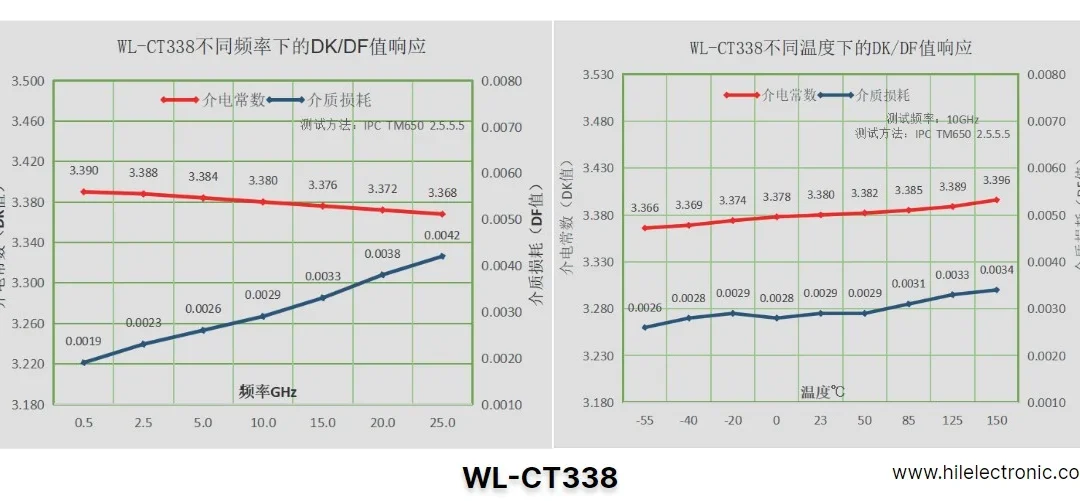
Custom WL-CT338 PCBs: Unlocking Performance for High-Tech Industries
At Highleap Electronic, we specialize in providing custom...

Custom Flex Board Production: Ultra-Long, Extra-Large, and Multi-Layer Designs
Flex boards, also known as flexible circuit boards (FPCs),...

Multilayer Flex PCB Manufacturing One-Stop Service
In today’s world of compact, high-performance, and...
How to get a quote for PCBs
Let us run DFM/DFA analysis for you and get back to you with a report.
You can upload your files securely through our website.
We require the following information in order to give you a quote:
-
- Gerber, ODB++, or .pcb, spec.
- BOM list if you require assembly
- Quantity
- Turn time
In addition to PCB manufacturing, we offer a comprehensive range of electronic services, including PCB design, PCBA (Printed Circuit Board Assembly), and turnkey solutions. Whether you need help with prototyping, design verification, component sourcing, or mass production, we provide end-to-end support to ensure your project’s success. For PCBA services, please provide your BOM (Bill of Materials) and any specific assembly instructions. We also offer DFM/DFA analysis to optimize your designs for manufacturability and assembly, ensuring a smooth production process.